


Mikroelektronika d.o.o.
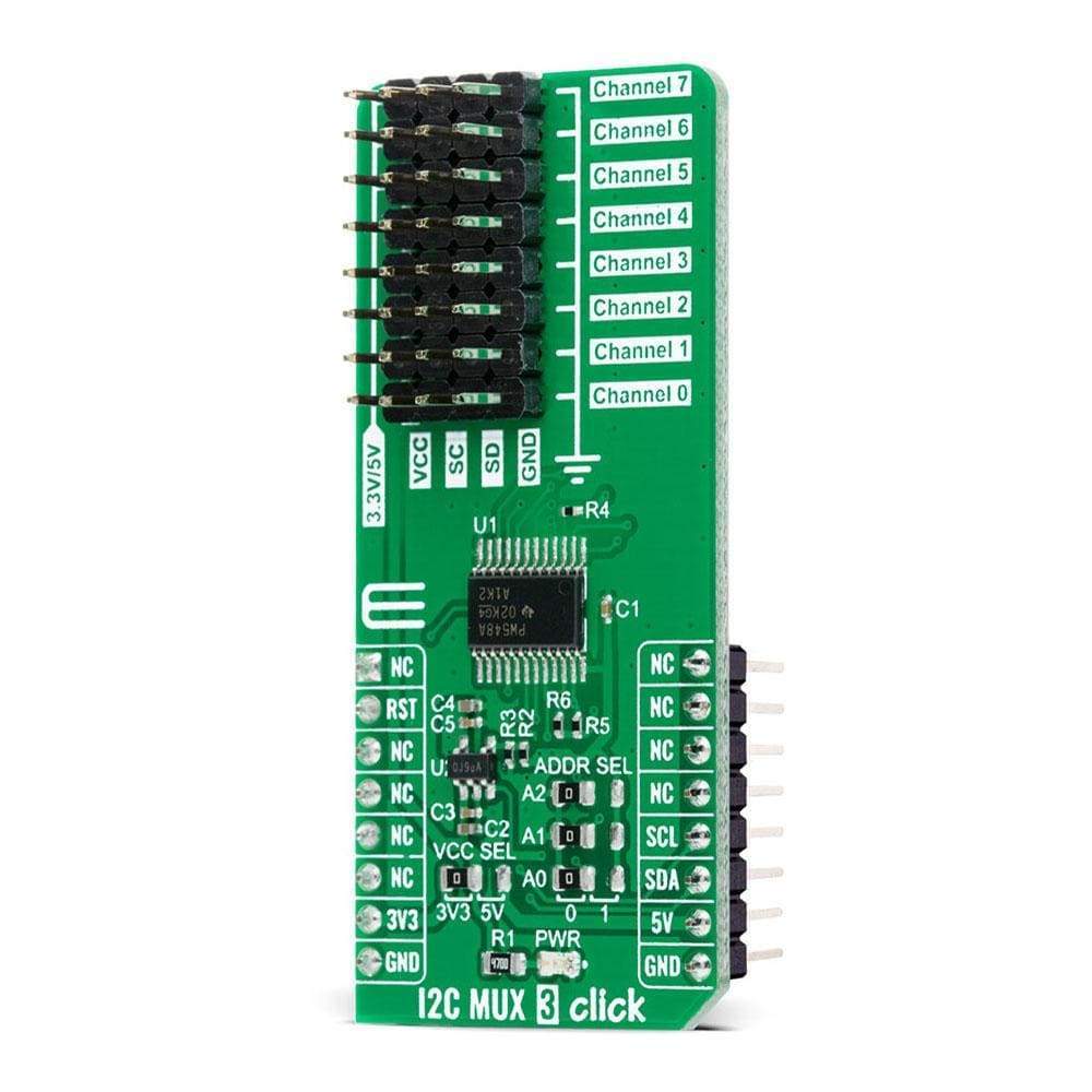
I2C MUX 3 Click Board™
I2C MUX 3 Click Board™
SKU: MIKROE-4262
Couldn't load pickup availability
Overview
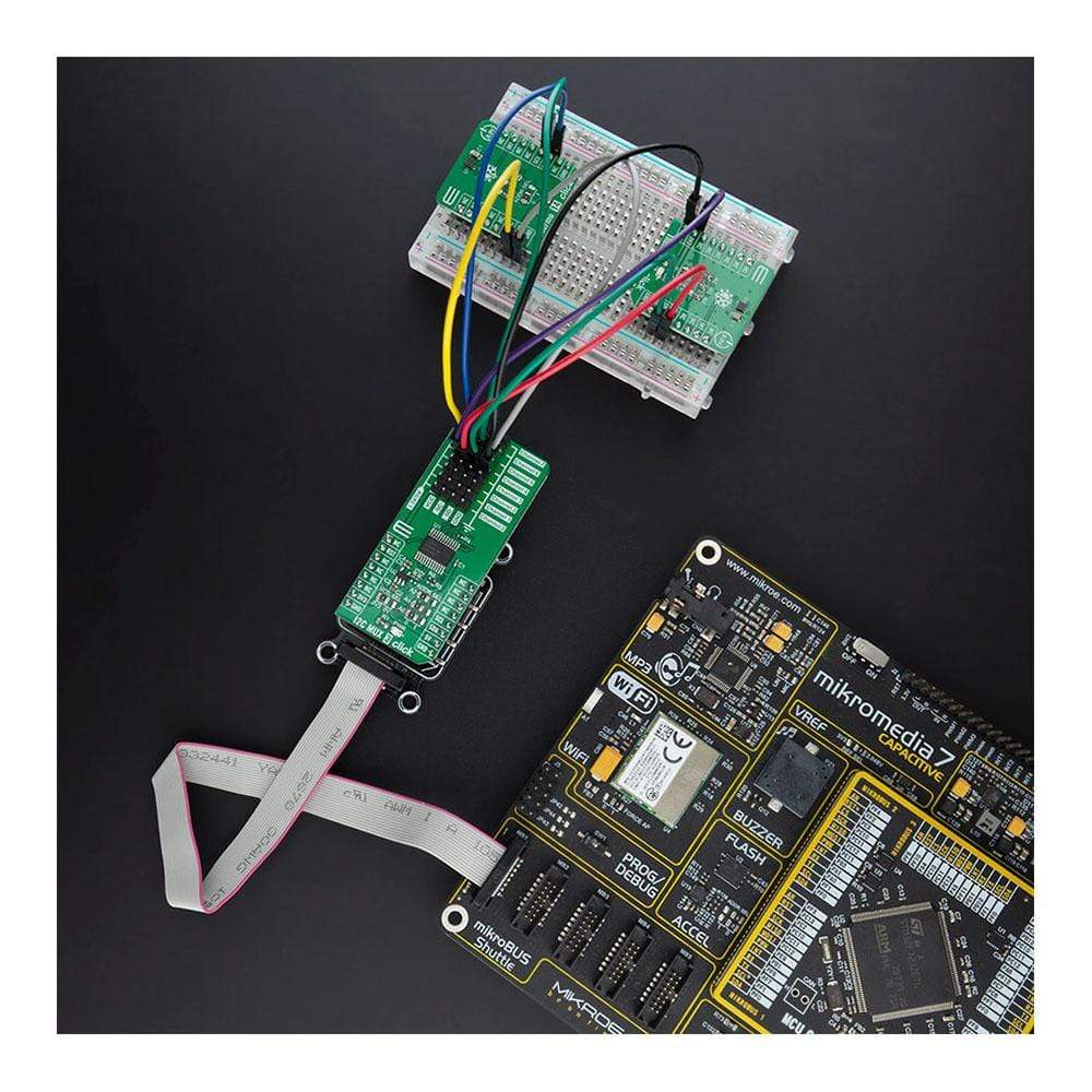
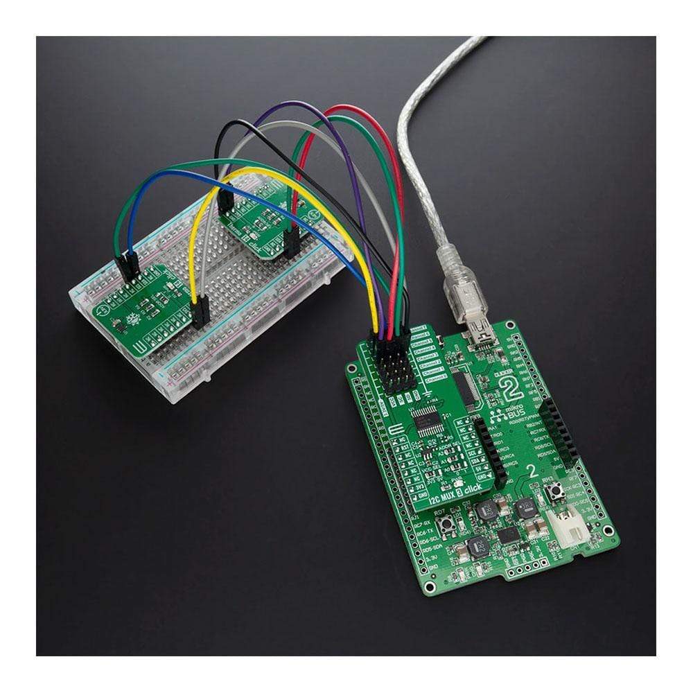
The I2C MUX 3 Click Board™ is a compact add-on board that contains eight bidirectional translating switches dedicated for applications with I2C slave address conflicts. This board features the TCA9548APWR, a low voltage 8-channel I2C bus switch with an active-low reset input from Texas Instruments. It possesses three programmable address pins that allow up to eight TCA9548APWR devices, supports hot insertion, has a low Stand-by current, and no glitch during Power-Up with all switch channels deselected. This Click Board™ is suitable to work with I2C interfaces for applications such as fault isolation, address conflict, level translation, or broadcast communication (servers, routers...).
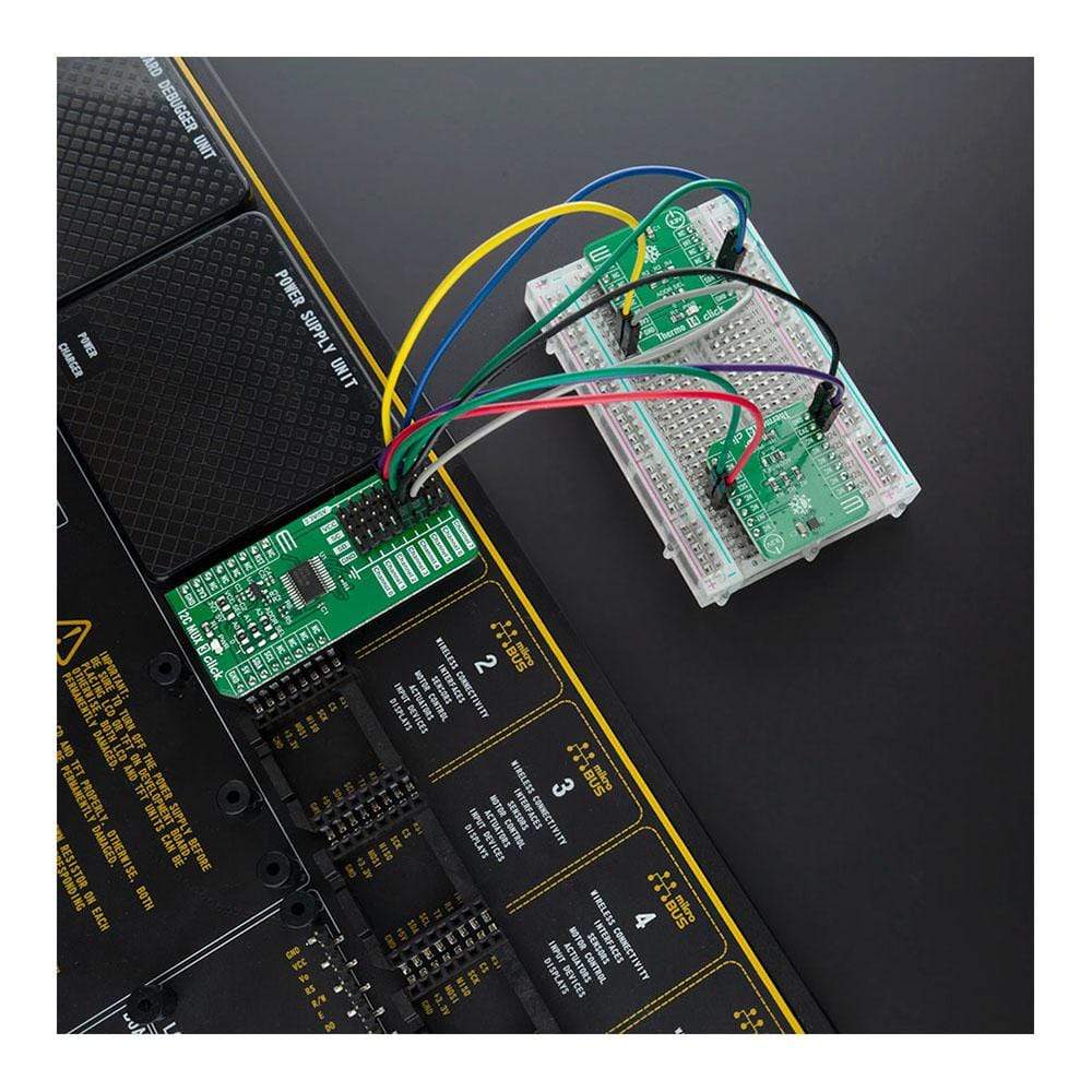
The I2C MUX 3 Click Board™ is supported by a mikroSDK compliant library, which includes functions that simplify software development. This Click Board™ comes as a fully tested product, ready to be used on a system equipped with the mikroBUS™ socket.
Downloads
How Does The I2C MUX 3 Click Board™ Work?
The I2C MUX 3 Click Board™ is based on the TCA9548APWR, a low voltage eight bidirectional translating switches with an active-low reset input controlled through the I2C serial interface from Texas Instruments. The master SCL/SDA signal pair is directed to eight channels of slave devices, SC0/SD0-SC7/SD7, where any individual downstream channel can be selected as well as any combination of the eight channels. It features I2C control using a single 8-bit control register in which each bit controls the enabling and disabling of one of the corresponding 8 switch channels for I2C data flow.
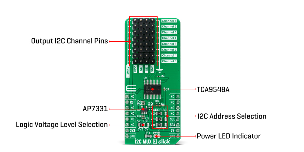
The I2C MUX 3 Click Board™ includes a low dropout linear regulator AP7331 from Diodes Incorporated to provide the 2.45V supply voltage for the TCA9548APWR. When the TCA9548APWR is turned on for the first time or anytime the device needs to be reset by cycling the power supply, which means that the Power-On reset requirements must be followed to ensure the I2C bus logic is initialized properly. Additionally, if communication on the I2C bus enters a fault state, the TCA9548APWR can be reset to resume normal operation using the RST pin feature or by a Power-On reset which results from cycling power to the device.
The I2C MUX 3 Click Board™ communicates with MCU using the standard I2C 2-Wire interface that supports Standard-Mode (100 kHz) and Fast-Mode (400 kHz) operation. The TCA9548APWR has a 7-bit slave address with the first five MSBs fixed to 1110. The address pins A0, A1 and A2 are programmed by the user and determines the value of the last three LSBs of the slave address which can be selected by onboard SMD jumpers labelled as ADDR SEL allowing selection of the slave address LSBs. It also has an active-low reset signal routed on the RST pin of the mikroBUS™ socket used to recover from a bus-fault condition. When this signal is asserted low the TCA9548APWR resets its registers alongside with I2C state machine and deselects all channels.
The I2C MUX 3 Click Board™ is designed to be operated with both 3.3V and 5V logic voltage levels that can be selected via VCC SEL jumper. This allows for both 3.3V and 5V capable MCUs to use the I2C communication lines properly. More information about the TCA9548APWR can be found in the attached datasheet. However, the Click board™ comes equipped with a library that contains easy to use functions and a usage example that may be used as a reference for further development.
SPECIFICATIONS
| Type | I2C |
| Applications | Can be used with I2C interfaces for applications such as fault isolation, address conflict, level translation, or broadcast communication (servers, routers...). |
| On-board modules | The I2C MUX 3 Click Board™ is based on the TCA9548APWR, a low voltage eight bidirectional translating switches with an active-low reset input controlled through the I2C serial interface from Texas Instruments. |
| Key Features | 1-to-8 bidirectional translating switches, low Stand-By current, support hot insertion, deselected channels during Power-Up, and more. |
| Interface | I2C |
| Compatibility | mikroBUS |
| Click board size | L (57.15 x 25.4 mm) |
| Input Voltage | 3.3V or 5V |
PINOUT DIAGRAM
This table shows how the pinout of the I2C MUX 3 Click Board™ corresponds to the pinout on the mikroBUS™ socket (the latter shown in the two middle columns).
| Notes | Pin | Pin | Notes | ||||
|---|---|---|---|---|---|---|---|
| NC | 1 | AN | PWM | 16 | NC | ||
| Reset | RST | 2 | RST | INT | 15 | NC | |
| NC | 3 | CS | RX | 14 | NC | ||
| NC | 4 | SCK | TX | 13 | NC | ||
| NC | 5 | MISO | SCL | 12 | SCL | I2C Clock | |
| NC | 6 | MOSI | SDA | 11 | SDA | I2C Data | |
| Power Supply | 3.3V | 7 | 3.3V | 5V | 10 | 5V | Power Supply |
| Ground | GND | 8 | GND | GND | 9 | GND | Ground |
ONBOARD SETTINGS AND INDICATORS
| Label | Name | Default | Description |
|---|---|---|---|
| LD1 | PWR | - | Power LED Indicator |
| JP1 | VCC SEL | Left | Power Supply Voltage Selection 3V3/5V: Left position 3V3, Right position 5V |
| JP2-JP4 | ADDR SEL | Left | Communication interface selection: Left position 0, Right position 1 |
| J1-J8 | - | - | Output I2C Channel Pins |
I2C MUX 3 CLICK ELECTRICAL SPECIFICATIONS
| Description | Min | Typ | Max | Unit |
|---|---|---|---|---|
| Supply Voltage | -0.5 | - | 7 | V |
| Maximum Output Current | -25 | - | - | mA |
| Maximum Frequency | - | - | 400 | kHz |
| Operating Temperature Range | -40 | - | +125 | °C |
| General Information | |
|---|---|
Part Number (SKU) |
MIKROE-4262
|
Manufacturer |
|
| Physical and Mechanical | |
Weight |
0.021 kg
|
| Other | |
EAN |
8606027380488
|
Frequently Asked Questions
Have a Question?
Be the first to ask a question about this.