


Mikroelektronika d.o.o.
6DOF IMU 14 Click Board™
6DOF IMU 14 Click Board™
SKU: MIKROE-4237
Couldn't load pickup availability
Overview
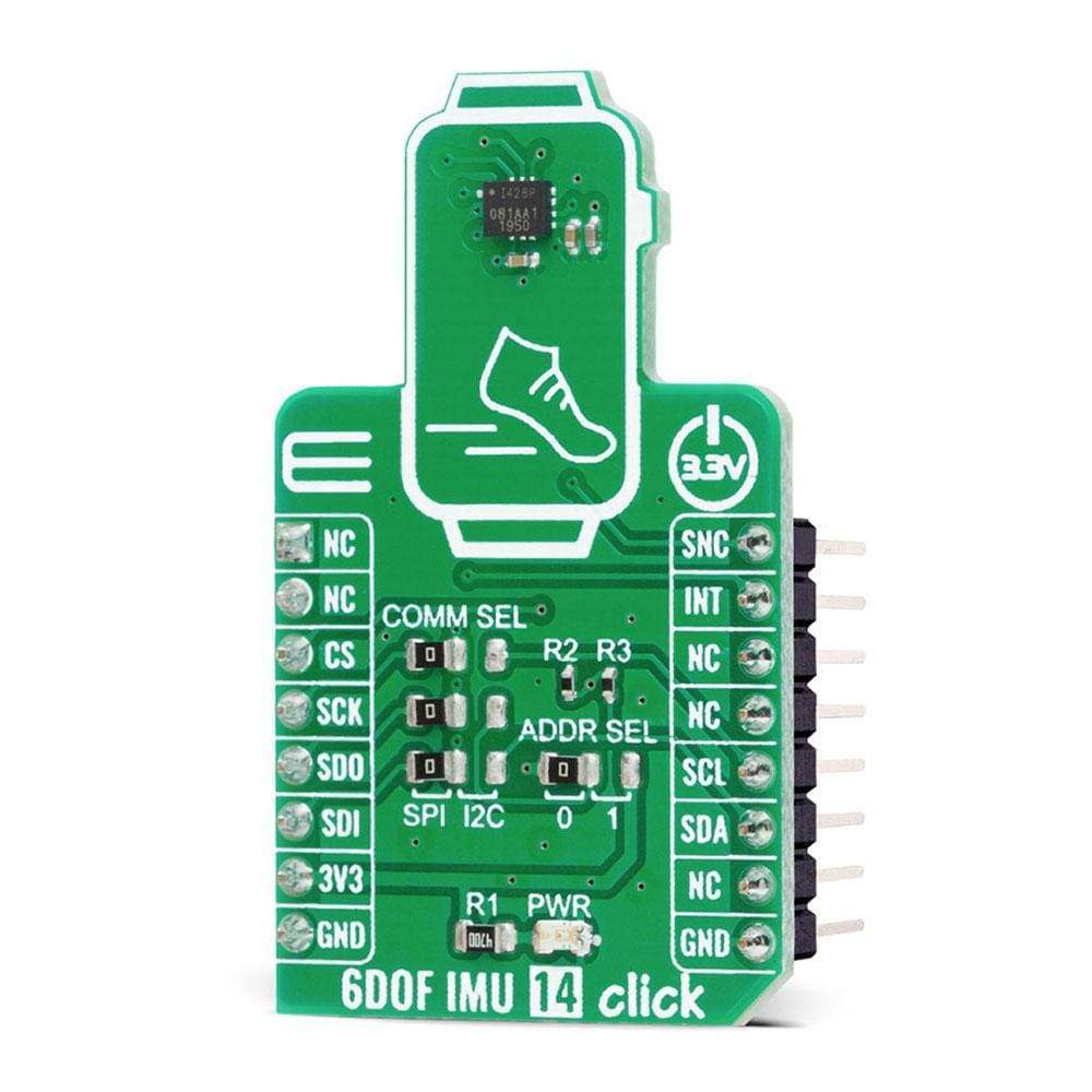
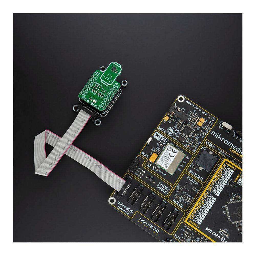
The 6DOF IMU 14 Click Board™ is a compact add-on board that contains a 6-axis MEMS motion tracking device combining a 3-axis gyroscope and a 3-axis accelerometer. This board features the ICM-42688-P, high precision 6-axis MEMS motion tracking device, from TDK InvenSense. It has a configurable host interface that supports both I2C and SPI serial communication, features a 2 kB FIFO and 2 programmable interrupts with ultra-low-power Wake-on-Motion support to minimize system power consumption. This Click Board™ is an excellent choice for applications like gesture recognition, activity classification, and pedometer, along with programmable digital filters, and an embedded temperature sensor.
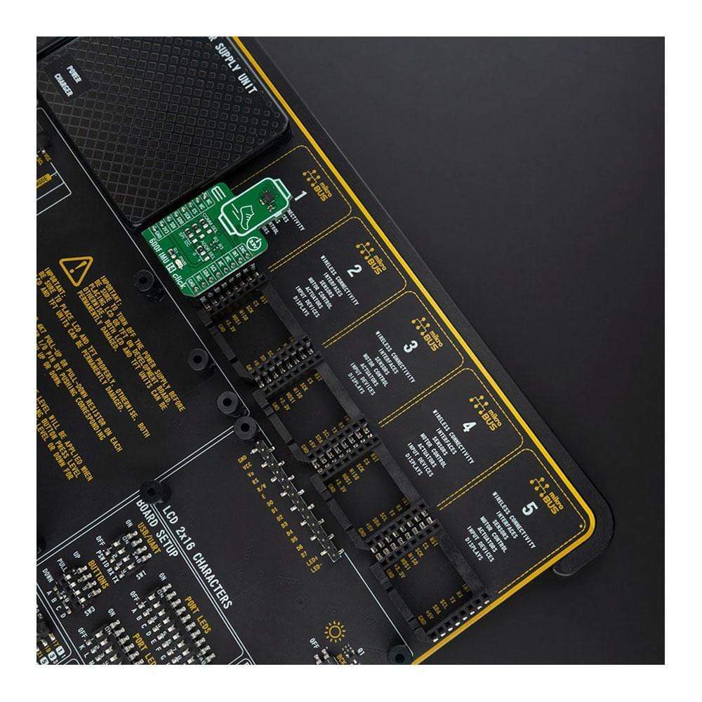
The 6DOF IMU 14 Click is supported by a mikroSDK compliant library, which includes functions that simplify software development. This Click Board™ comes as a fully tested product, ready to be used on a system equipped with the mikroBUS™ socket.
Downloads
How Does The 6DOF IMU 14 Click Board™ Work?
The 6DOF IMU 14 Click Board™ is based on the ICM-42688-P, high precision 6-axis MEMS motion tracking device, from TDK InvenSense. It features a 2kB FIFO that can lower the traffic on the serial bus interface, and reduce power consumption by allowing the system processor to burst read sensor data, and then go into a low-power mode. It also supports external clock input for highly accurate 31kHz to 50kHz clock, which helps to reduce system-level sensitivity error and improve orientation measurement from gyroscope data. ICM-42688-P includes an industry-first 20-bits data format support in FIFO for high-data resolution. This FIFO format encapsulates 19-bits of gyroscope data and 18-bits of accelerometer data.

The 6DOF IMU 14 Click Board™ includes a vibratory MEMS rate gyroscope that detects rotation about the X-, Y-, and Z- axes, and a 3-axis MEMS accelerometer. The full-scale range of the gyro sensors may be digitally programmed from ±15.625 up to ±2000 degrees per second (DPS). The ICM-42688-P architecture reduces the accelerometer's sensitivity to fabrication variations as well as to thermal drift. When the device is placed on a flat surface, it will measure 0g on the X- and Y-axes and +1g on the Z-axis. The full-scale range of the digital output can be adjusted from ±2g, up to ±16g.
The ICM-42688-P has a programmable interrupt system that can generate an interrupt signal. There are two interrupt outputs in which one of them represents frame synchronization input routed to the PWM pins on the mikroBUS™. An interrupt can be triggered while switching clock sources, when new data is available for reading (from the FIFO and data registers), during accelerometer events, FIFO watermark and overflow.
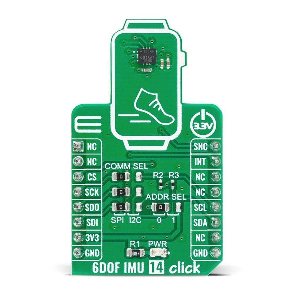
6DOF IMU 14 Click provides the possibility of using both I2C and SPI interfaces with a maximum frequency of 1MHz for I2C and 25MHz for SPI communication. The selection can be done by positioning SMD jumpers labeled as COMM SEL to an appropriate position. Note that all the jumpers must be placed to the same side, or else the Click board™ may become unresponsive. While the I2C interface is selected, the ICM-42688-P allows the choice of the least significant bit (LSB) of its I2C slave address. This can be done by using the SMD jumper labeled as ADDR SEL.
This Click Board™ is designed to be operated only with a 3.3V logic level. A proper logic voltage level conversion should be performed before the Click board™ is used with MCUs with different logic levels.
SPECIFICATIONS
| Type | Motion |
| Applications | Can be used for applications like gesture recognition, activity classification, and pedometer, along with programmable digital filters, and an embedded temperature sensor. |
| On-board modules | 6DOF IMU 14 Click is based on the ICM-42688-P, high precision 6-axis MEMS motion tracking device, from TDK InvenSense. |
| Key Features | Low power consumption, high precission, user-programmable digital filters, user scallable gyro/accel full-scale range, 20,000 g shock tolerant and more. |
| Interface | I2C,SPI |
| Compatibility | mikroBUS |
| Click board size | S (28.6 x 25.4 mm) |
| Input Voltage | 3.3V |
PINOUT DIAGRAM
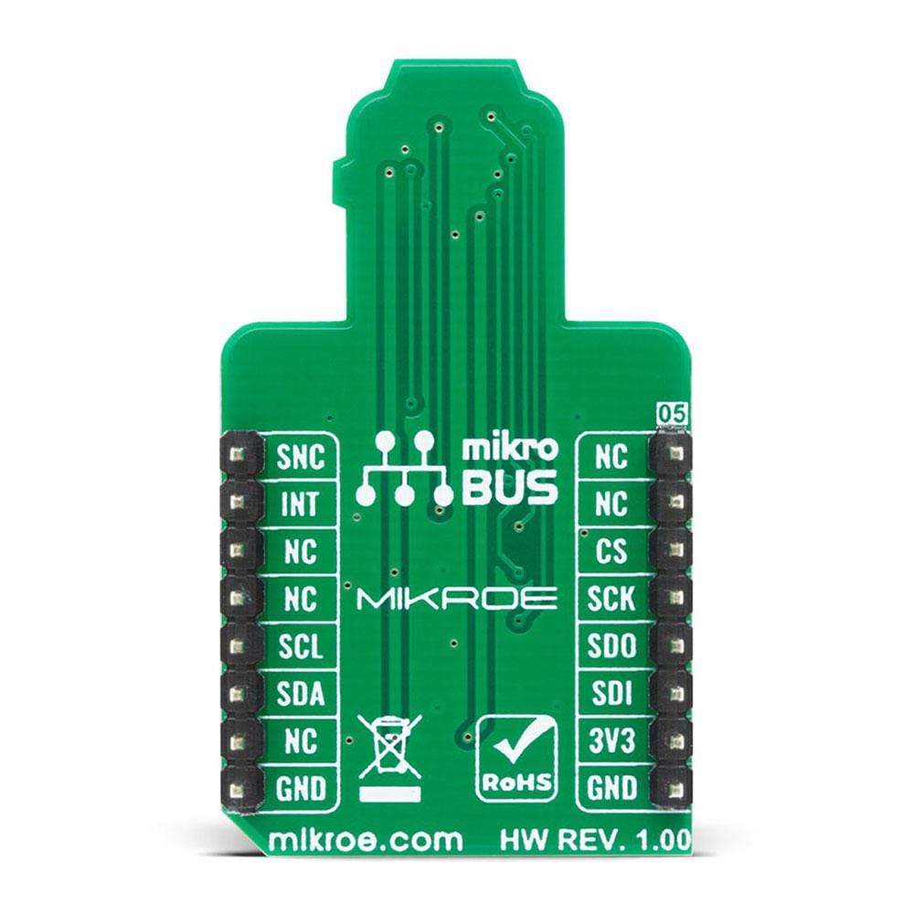
This table shows how the pinout on 6DOF IMU 14 Click corresponds to the pinout on the mikroBUS™ socket (the latter shown in the two middle columns).
| Notes | Pin | Pin | Notes | ||||
|---|---|---|---|---|---|---|---|
| NC | 1 | AN | PWM | 16 | SNC | External sync | |
| NC | 2 | RST | INT | 15 | INT | Interrupt | |
| SPI Chip Select | CS | 3 | CS | RX | 14 | NC | |
| SPI Clock | SCK | 4 | SCK | TX | 13 | NC | |
| SPI Data OUT | SDO | 5 | MISO | SCL | 12 | SCL | I2C Clock |
| SPI Data IN | SDI | 6 | MOSI | SDA | 11 | SDA | I2C Data |
| Power Supply | 3.3V | 7 | 3.3V | 5V | 10 | NC | |
| Ground | GND | 8 | GND | GND | 9 | GND | Ground |
ONBOARD SETTINGS AND INDICATORS
| Label | Name | Default | Description |
|---|---|---|---|
| LD1 | PWR | - | Power LED Indicator |
| JP1 | ADDR SEL | Left | I2C Address Selection: Left position 0, Right position 1 |
| JP2-JP4 | COMM SEL | Left | Communication Interface Selection: Left position SPI, Right position I2C |
6DOF IMU 14 CLICK ELECTRICAL SPECIFICATIONS
| Description | Min | Typ | Max | Unit |
|---|---|---|---|---|
| Supply Voltage | -0.5 | 3.3 | 4 | V |
| I2C Clock Frequency | - | - | 1 | MHz |
| SPI Clock Frequency | - | - | 24 | MHz |
| External Clock Source | 31 | 32 | 50 | kHz |
| Operating Temperature Range | -40 | - | +85 | °C |
| General Information | |
|---|---|
Part Number (SKU) |
MIKROE-4237
|
Manufacturer |
|
| Physical and Mechanical | |
Weight |
0.019 kg
|
| Other | |
EAN |
8606027380273
|
Frequently Asked Questions
Have a Question?
Be the first to ask a question about this.