


Mikroelektronika d.o.o.
I2C Extend Click Board™
I2C Extend Click Board™
SKU: MIKROE-4207
Couldn't load pickup availability
Overview
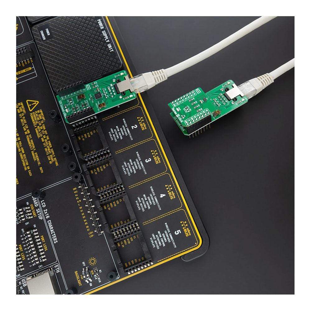
The I2C Extend Click Board™ is a compact add-on board for applications that require extending the I2C communication bus over a long distance. This board features the LTC4331 - an I2C slave device extender over a rugged differential link, from Analog Devices. It is a point-to-point SMBus compatible I2C slave device extender, designed for operation in high noise industrial environments while supporting Up to 1MHz serial clock, ±40kV ESD protection on link pins, selectable link baud rates and many more. All these features make I2C Extend Click an excellent choice for various applications that require extending the I2C bus over a long distance, such as sensor installation, industrial control, lighting system control, sound system control, and more.
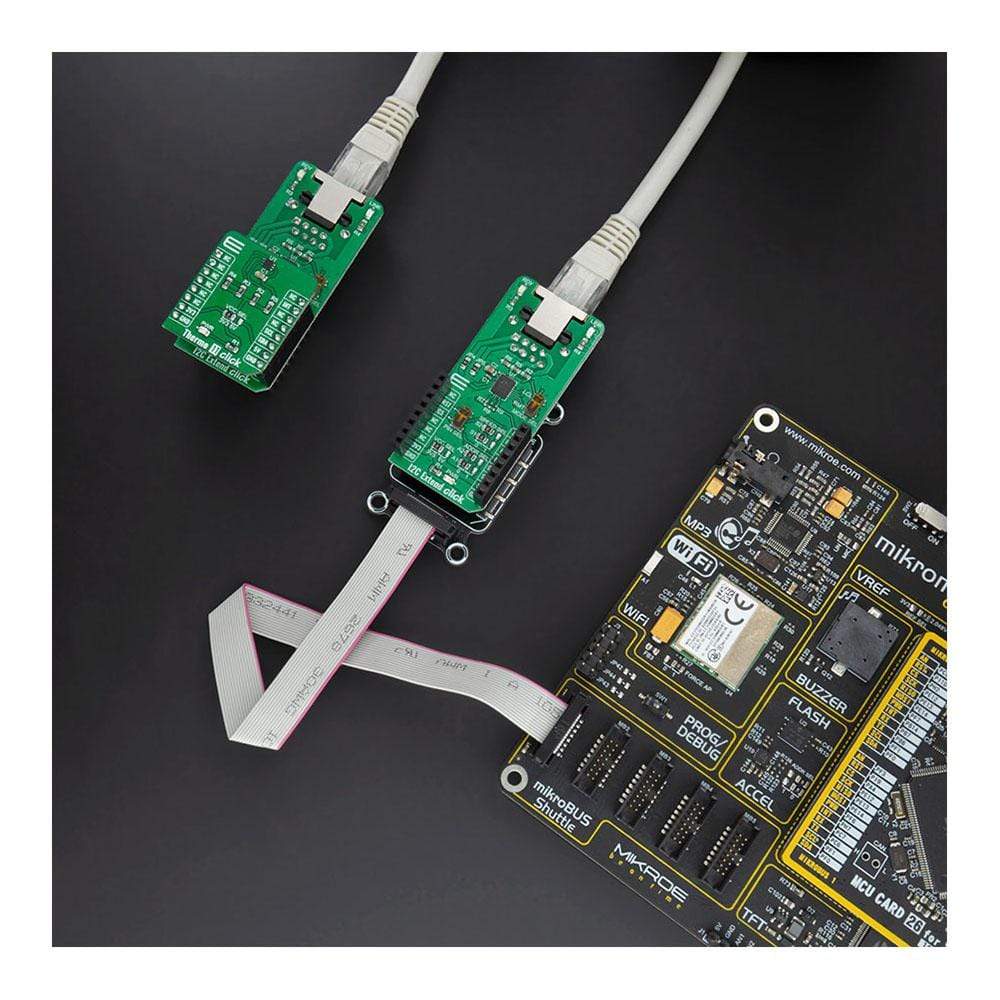
The I2C Extend Click Board™ is supported by a mikroSDK compliant library, which includes functions that simplify software development. This Click Board™ comes as a fully tested product, ready to be used on a system equipped with the mikroBUS™ socket.
Downloads
How Does The I2C Extend Click Board™ Work?
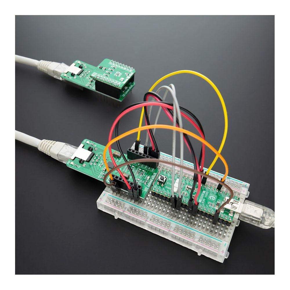
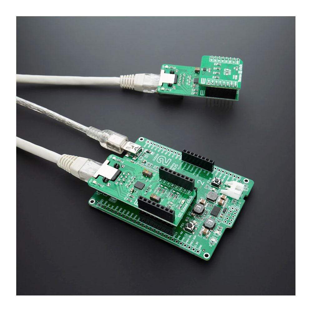
The I2C Extend Click Board™ is based on the LTC4331, which is a point-to-point compatible I2C slave device extender designed for operation in high noise industrial environments. Using a ±60V fault protected differential transceiver, the LTC4331 can extend an I2C/SMBus bus, including remote interrupt function and a control signal, over a single twisted pair differential link. Thanks to selectable link baud rates, the I2C bus can be extended up to 1200m, depending on the link speed and external factors such as environmental noise level, humidity, cable quality, etc. Standard twisted-pair cables with RJ45 connectors can be used, the same as in the ethernet devices, etc.
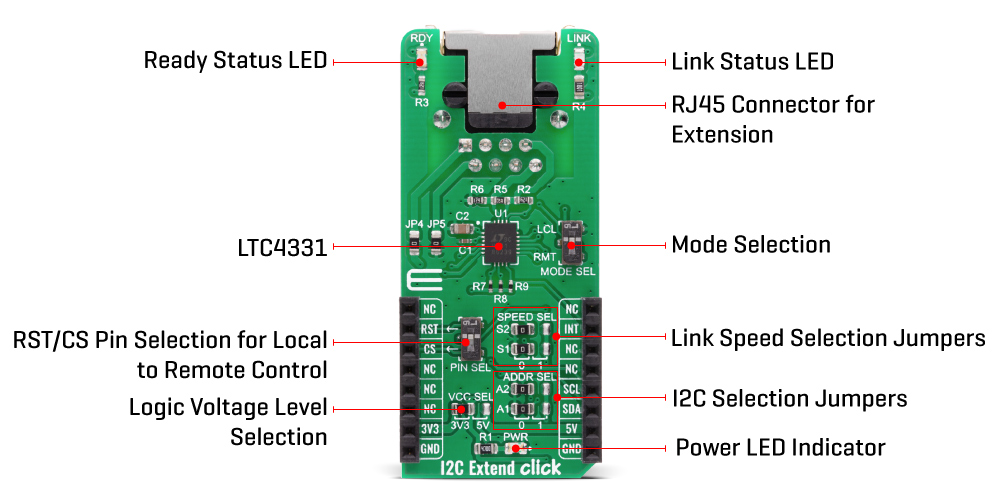
Besides the I2C protocol extension, I2C Extend Click Board™ also supports local to remote control and interrupt functions. Local to remote control ensures that the values set on the local side CTRL pin propagate to the remote side CTRL pin over the differential link. Users can choose pin on the mikroBUS™ socket used for that purpose (CS or RST), using the onboard jumper named PIN SEL. Interrupt pin acts as an open-drain output in local mode and an input in remote mode. Basically, an interrupt signal on the INT pin in the I2C Extend Click is mirrored from the remote network to the local network using the differential link. On the remote side INT is an input pin that can be connected to remote I2C slave devices, while on the local side, it is operating as an open-drain output that can be connected to a shared local interrupt line.
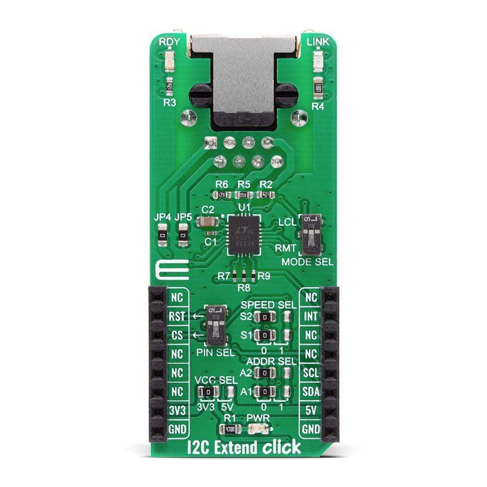
Because of the dual functionality of the I2C Extend Click, the user needs to set the mode of operation of the Click board™. That is easily achieved using the onboard MODE switch, with two positions: local mode (LCL), where this Click board™ is in I2C slave mode and remote mode (RMT) where this Click board™ is in I2C master mode. Besides mode selection, I2C Extend Click can also link speed and I2C address selection jumpers onboard, named "SPEED SEL" and "ADDR SEL", respectively.
The I2C Extend Click Board™ has Link status (LINK) and ready status (RDY) LEDs, making troubleshooting as easy as possible. In remote mode, LINK LED is active when the device establishes link communication. When in local mode, LINK LED is active after the LTC4331's I2C interface has joined the I2C bus in addition to establishing link communication.The RDY LED is active after the device's I2C interface has joined the bus.
The I2C Extend Click Board™ is designed to operate with both 3.3V and 5V logic levels that can be selected via VCC SEL jumper. This allows for both 3.3V and 5V capable MCUs to use the I2C communication lines properly.
SPECIFICATIONS
| Type | Interface |
| Applications | Excellent choice for various applications that require extending the I2C bus over a long distance, such as sensor installation, industrial control, lighting system control, sound system control, and more. |
| On-board modules | LTC4331 - an I2C slave device extender over rugged differential link, from Analog Devices |
| Key Features | Designed for operation in high noise industrial environments while supporting Up to 1MHz serial clock, ±40kV ESD protection on link pins, selectable link baud rates and many more |
| Interface | GPIO,I2C |
| Compatibility | mikroBUS |
| Click board size | L (57.15 x 25.4 mm) |
| Input Voltage | 3.3V or 5V |
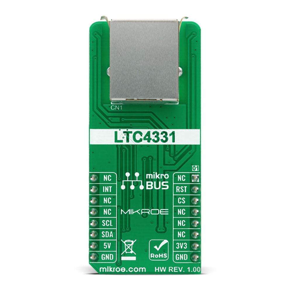
PINOUT DIAGRAM
This table shows how the pinout of the I2C Extend Click Board™ corresponds to the pinout on the mikroBUS™ socket (the latter shown in the two middle columns).
| Notes | Pin | Pin | Notes | ||||
|---|---|---|---|---|---|---|---|
| NC | 1 | AN | PWM | 16 | NC | ||
| Reset pin | RST | 2 | RST | INT | 15 | INT | Interrupt pin |
| SPI Chip Select | CS | 3 | CS | RX | 14 | NC | |
| NC | 4 | SCK | TX | 13 | NC | ||
| NC | 5 | MISO | SCL | 12 | SCL | I2C Clock | |
| NC | 6 | MOSI | SDA | 11 | SDA | I2C Data | |
| Power Supply | 3.3V | 7 | 3.3V | 5V | 10 | 5V | Power Supply |
| Ground | GND | 8 | GND | GND | 9 | GND | Ground |
ONBOARD SETTINGS AND INDICATORS
| Label | Name | Default | Description |
|---|---|---|---|
| LD1 | PWR | - | Power LED Indicator |
| LD2 | RDY | - | Ready status LED Indicator |
| LD3 | LINK | - | Link status LED Indicator |
| JP1 | VCC SEL | Left | Power Supply Voltage Selection: left position 3v3, right position 5v |
| JP2, JP3 | ADDR SEL | Left | Communication interface selection: left position 0, right position 1 |
| JP6, JP7 | SPEED SEL | Left | Communication speed selection: left position 0, right position 1 |
| SW1 | PIN SEL | - | Local to remote control pin selection |
I2C EXTEND CLICK ELECTRICAL SPECIFICATIONS
| Description | Min | Typ | Max | Unit |
|---|---|---|---|---|
| Supply Voltage | 3 | 3.3 | 5.5 | V |
| Extension Range | - | - | 1200 | m |
| Serial Clock Frequency | - | - | 1 | MHz |
| General Information | |
|---|---|
Part Number (SKU) |
MIKROE-4207
|
Manufacturer |
|
| Physical and Mechanical | |
Weight |
0.023 kg
|
| Other | |
EAN |
8606027380181
|
Frequently Asked Questions
Have a Question?
Be the first to ask a question about this.