


Mikroelektronika d.o.o.
RTC 9 Click Board™
RTC 9 Click Board™
SKU: MIKROE-4121
Couldn't load pickup availability
Key Features
Overview
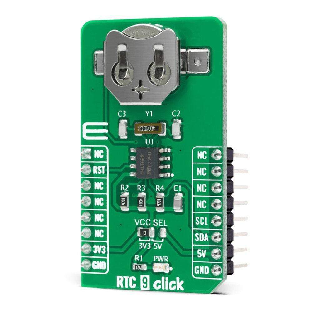
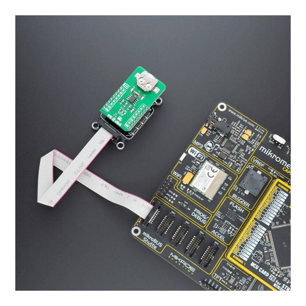
The RTC 9 Click Board™ is a real-time clock module that has an extremely low power consumption, allowing it to be used with a single button cell battery for an extended period of time. This board features the M41T82, real-time clock (RTC) with battery switchover, from ST Microelectronics. It features factory-calibrated accuracy of ±5 ppm typically, automatic switchover and reset output circuitry, programmable alarm with interrupt function, and more.
All these features make RTC 9 Click Board™ an excellent choice for manufacturers for applications such as portable applications, logging devices, wearables, medical equipment, and similar.
Downloads
How Does The RTC 9 Click Board™Work?
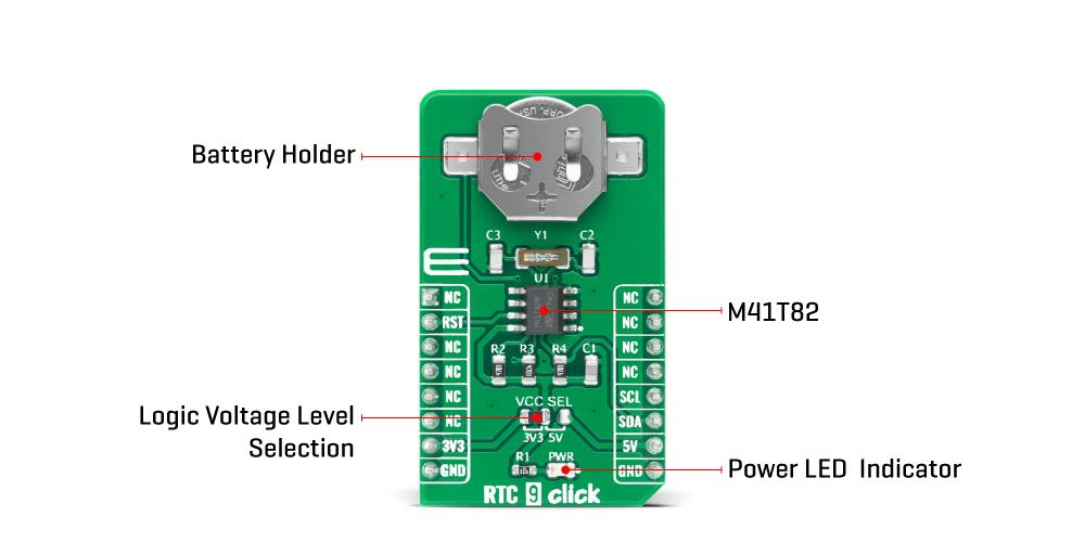
The RTC 9 Click Board™ is based on the M41T82, an extreme low power real-time clock/calendar (RTC) module from ST Microelectronics. Thanks to its high integration level, this module provides high time accuracy, factory calibrated to ±5 ppm even after two reflows, with a very low count of external components required. It has a full RTC function, offering programmable counters, alarms, and an interrupt engine with selectable event reporting sources. The operational parameters are stored within the internal user SRAM memory, which is battery-backed, thus allowing their persistence in the event of the complete power failure.
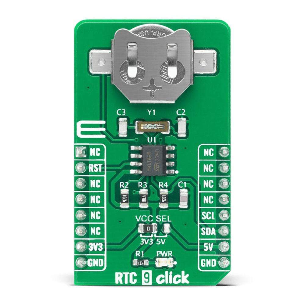
M41T82 features a built-in 32.768 kHz oscillator. However, the RTC 9 Click Board™ has an external oscillator too, in order to achieve the best accuracy possible. Eight bytes of the register map are used for the clock/calendar function and are configured in binary-coded decimal (BCD) format. An additional 17 bytes of the register map provide status/control of the two alarms, watchdog, 8-bit counter, and square wave functions. An additional seven bytes are made available as user SRAM. M41T82 supports the I2C communication interface, which is also used on the RTC 9 Click Board™ for communicating with the main microcontroller through the mikroBUS socket.
Functions available to the user include a non-volatile, time-of-day clock/calendar, two alarm interrupts, watchdog timer, programmable 8-bit counter, and square wave outputs. The eight clock address locations contain the century, year, month, date, day, hour, minute, second, and tenths/hundredths of a second in 24-hour BCD format. Corrections for 28, 29 (leap year), 30, and 31 day months are made automatically.
The RTC 9 Click Board™ is designed to be operated with both 3.3V and 5V logic levels that can be selected via VCC SEL jumper. This allows for both 3.3V and 5V capable MCUs to use the I2C communication lines properly.
SPECIFICATIONS
| Type | RTC |
| Applications | The RTC 9 Click Board™ is a perfect solution for the development of the IoT, wearable and portable devices, logging devices, industrial and health-related time metering applications, and all the other applications that require an accurate time-base for various purposes. |
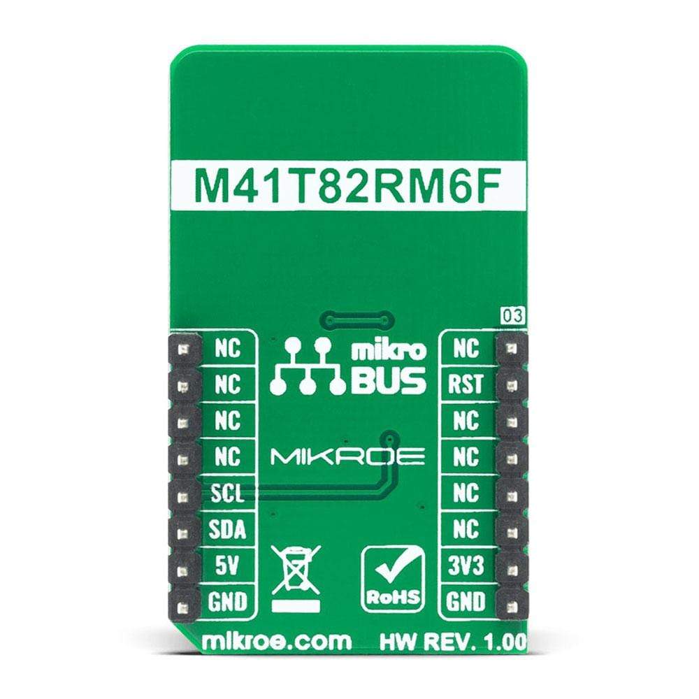
| On-board modules | M41T82, real-time clock (RTC) with battery switchover, from ST Microelectronics. |
| Key Features | Factory-calibrated accuracy of ±5 ppm typically, automatic switchover and reset output circuitry, programmable alarm with interrupt function, and more |
| Interface | I2C |
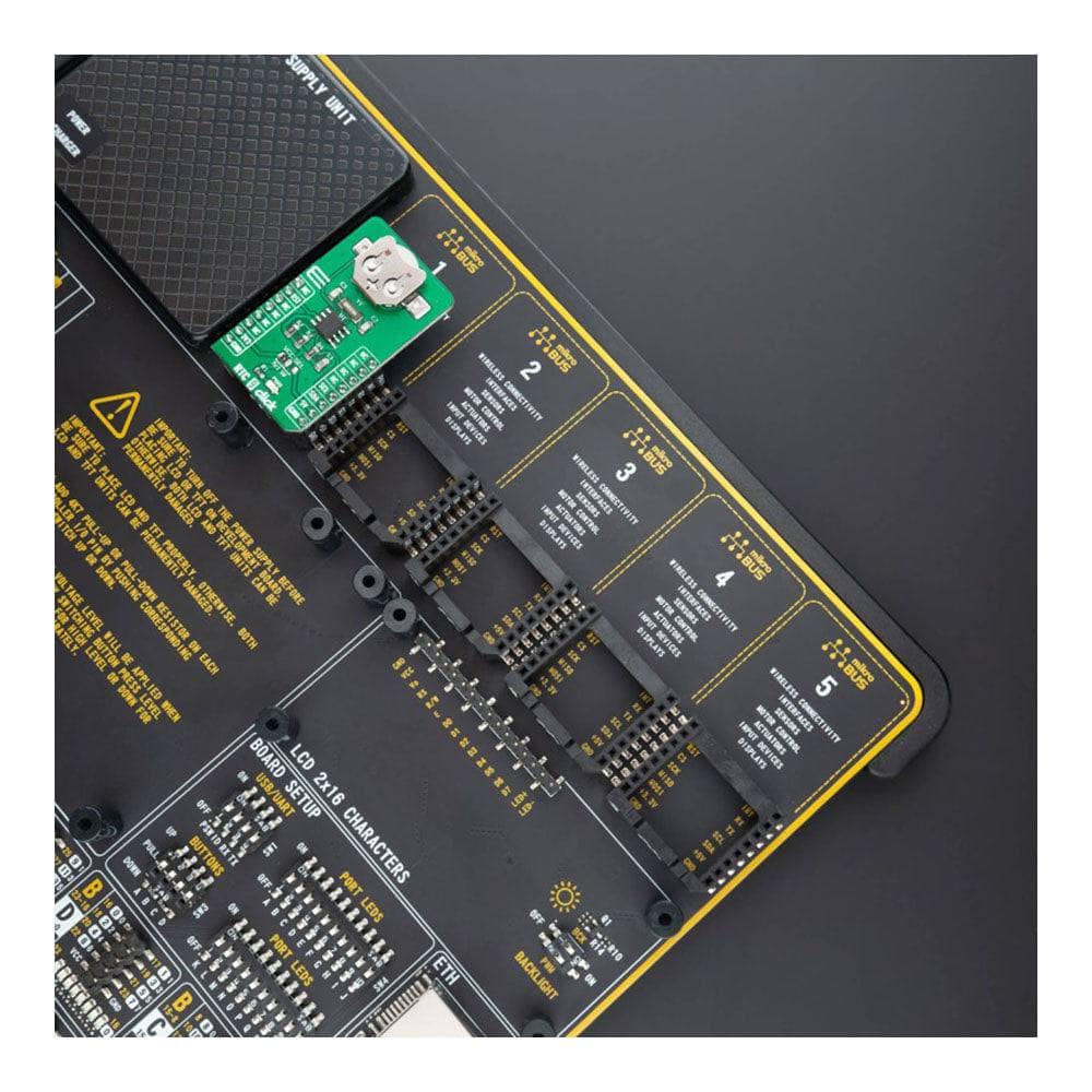
| Compatibility | mikroBUS |
| Click board size | M (42.9 x 25.4 mm) |
| Input Voltage | 3.3V or 5V |
PINOUT DIAGRAM
This table shows how the pinout on the RTC 9 Click Board™ corresponds to the pinout on the mikroBUS™ socket (the latter shown in the two middle columns).
| Notes | Pin | Pin | Notes | ||||
|---|---|---|---|---|---|---|---|
| NC | 1 | AN | PWM | 16 | NC | ||
| Reset | RST | 2 | RST | INT | 15 | NC | |
| NC | 3 | CS | RX | 14 | NC | ||
| NC | 4 | SCK | TX | 13 | NC | ||
| NC | 5 | MISO | SCL | 12 | SCL | I2C Clock | |
| NC | 6 | MOSI | SDA | 11 | SDA | I2C Data | |
| Power Supply | 3.3V | 7 | 3.3V | 5V | 10 | 5V | Power Supply |
| Ground | GND | 8 | GND | GND | 9 | GND | Ground |
ONBOARD SETTINGS AND INDICATORS
| Label | Name | Default | Description |
|---|---|---|---|
| LD1 | PWR | - | Power LED Indicator |
| JP1 | VCC SEL | Left | Power Supply Voltage Selection 3V3/5V, left position 3v3, right position 5v |
RTC 9 CLICK ELECTRICAL SPECIFICATIONS
| Description | Min | Typ | Max | Unit |
|---|---|---|---|---|
| Supply Voltage (for R version) | 2.70 | 3.3 | 5.5 | V |
| Supply Current | - | 365 | - | nA |
| Accuracy | - | 5 | - | ppm |
| Operating Temperature Range | -40 | - | 85 | °C |
| General Information | |
|---|---|
Part Number (SKU) |
MIKROE-4121
|
Manufacturer |
|
| Physical and Mechanical | |
Weight |
0.019 kg
|
| Other | |
EAN |
8606027380075
|
Frequently Asked Questions
Have a Question?
Be the first to ask a question about this.