


Mikroelektronika d.o.o.
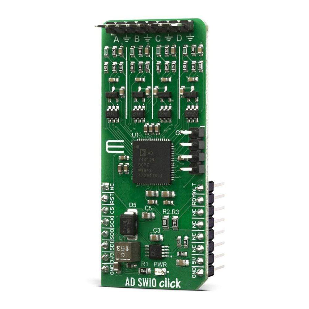
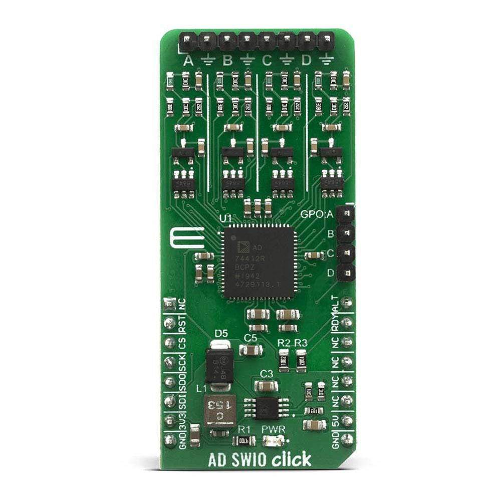
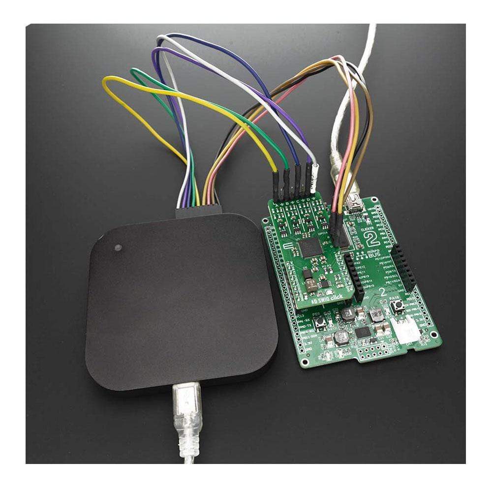
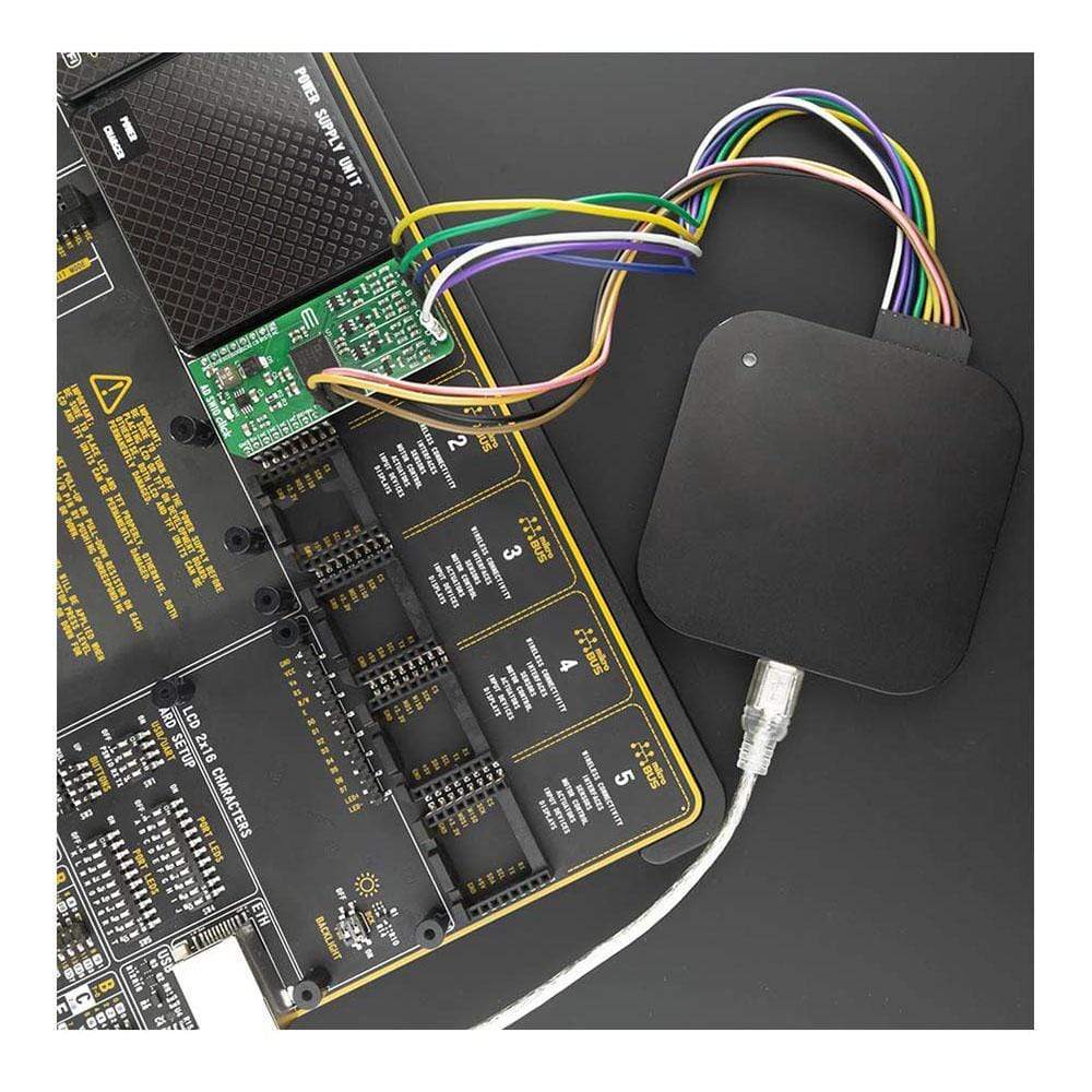
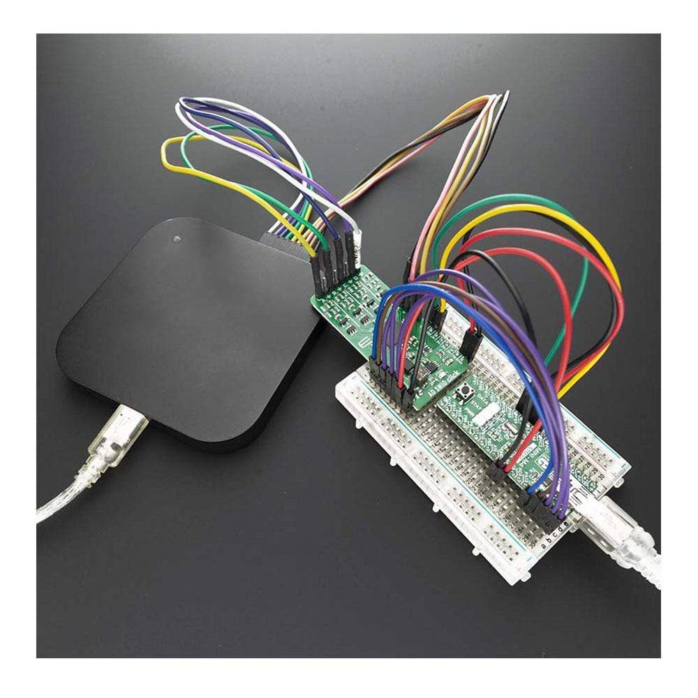
AD-SWIO Click Board™
AD-SWIO Click Board™
SKU: MIKROE-4081
Couldn't load pickup availability


Overview
The AD-SWIO Click Board™ is a quad-channel software-configurable input/output solution based on AD74412R. The AD74412R is a quad-channel software-configurable input/output integrated circuit for building and process control applications. The device provides a fully integrated single-chip solution for input and output operation.
The AD-SWIO Click Board™ contains four 13-bit DACs, one per chanal, and 16-bit Σ-∆ ADC. These options give a lot of flexibility in choosing functionality for analogue output, analogue input, digital input, resistance temperature detector (RTD), and thermocouple measurements integrated into a single chip solution with a serial peripheral interface (SPI).
Downloads
How Does The AD-SWIO Click Board™ Work?
The AD-SWIO Click Board™ features a 16-bit analog-to-digital converter (ADC), and 13-bit digital-to-analog converter (DAC) embed in AD74412R from Analog Devices. There are several modes related to the AD74412R. These modes are voltage output, current output, voltage input, externally powered current input, loop powered current input, external RTD measurement, digital input logic, and loop powered digital input.
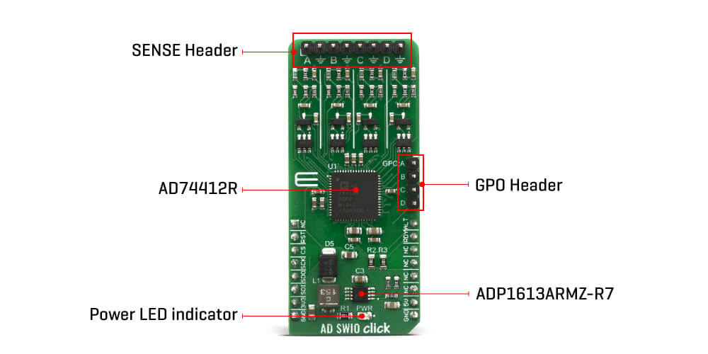
The ADC can measure either the voltage across the 100 Ω RSENSE or the voltage at the I/OP_x screw terminal of each channel. In high impedance mode, the ADC, by default, measures the voltage across the screw terminals (I/OP_x to I/ON_x) in a 0 V to 10 V range. The ADC also provides diagnostic information on user-selectable inputs such as supplies, internal die temperature, reference, and regulators.
The AD-SWIO Click Board™ has four GPO-x pins, one per channel ( GPO-A, GPO-B, GPO-C, GPO-D). Each channel GPO-x pin can be configured to the logic outputs of the digital input functions or a logic high or low output. The GPO-x pins can be set via the GPO_SELECT bits within the GPO_CONFIGx registers. The Click Board™ also contains LVIN ( Low Voltage Input) pin, the measurement voltage range on this pin is 0V to 2.5V.
The AD74412R contains four 13-bit DACs, one per channel. Each DAC core is a 13-bit string DAC. The architecture structure consists of a string of resistors, each with a value of R. The digital input code that is loaded to the DAC_CODEx registers determines which node on the string the voltage is tapped off from and fed into the output amplifier. This architecture is inherently monotonic and linear.
The AD74412R have short-circuit limit in voltage output mode is programmable per channel. The circuit minimizes glitching on the I/OP_x screw terminal when the AVDD supply is ramping or when the use case configuration is changed. This short-circuit limit, you can regulate with positive analog supply on AVDD pin, Output voltage on AD-SWIO Click Board™ is limited to +20V. The AD-SWIO Click Board™ is equipped with the ADP1613 step-up dc-to-dc switching converters with an integrated power switch capable of providing an output voltage as high as 20 V also from Analog Devices.
SPECIFICATIONS
| Type | SWIO,ADC-DAC |
| Applications | Applications Its a perfect choice for Process control, Factory automation, Motor drives, Building control systems. |
| On-board modules | AD74412R a quad-channel SWIO and ADP1613 step-up dc-to-dc switching converter all from Analog Devices |
| Key Features | Optimized for 16-bit ADC (Analog-to-Digital Converter) and 13-bit DAC (Digital-to-Analog Converter). |
| Interface | GPIO,SPI |
| Compatibility | mikroBUS |
| Click Board™ size | L (57.15 x 25.4 mm) |
| Input Voltage | 3.3V,5V |
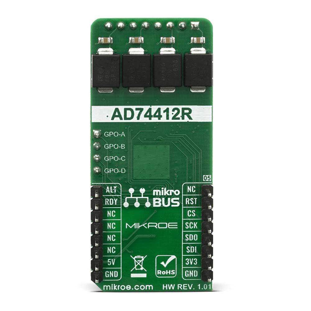
PINOUT DIAGRAM
This table shows how the pinout on the AD-SWIO Click Board™ corresponds to the pinout on the mikroBUS socket (the latter shown in the two middle columns).
| Notes | Pin | Pin | Notes | ||||
|---|---|---|---|---|---|---|---|
| NC | 1 | AN | PWM | 16 | ALT | Alert Status | |
| Reset | RST | 2 | RST | INT | 15 | RDY | Ready to read |
| SPI Chip Select | CS | 3 | CS | RX | 14 | NC | |
| SPI Clock | SCK | 4 | SCK | TX | 13 | NC | |
| SPI Data OUT | SDO | 5 | MISO | SCL | 12 | NC | |
| SPI Data IN | SDI | 6 | MOSI | SDA | 11 | NC | |
| Power Supply | 3.3V | 7 | 3.3V | 5V | 10 | 5V | Power Supply |
| Ground | GND | 8 | GND | GND | 9 | GND | Ground |
ONBOARD SETTINGS AND INDICATORS
| Label | Name | Default | Description |
|---|---|---|---|
| LD1 | PWR | - | Power LED Indicator |
| General Information | |
|---|---|
Part Number (SKU) |
MIKROE-4081
|
Manufacturer |
|
| Physical and Mechanical | |
Weight |
0.02 kg
|
| Other | |
EAN |
8606018717262
|
Frequently Asked Questions
Have a Question?
Be the first to ask a question about this.