


Mikroelektronika d.o.o.
Dual LIN Click Board™
Dual LIN Click Board™
SKU: MIKROE-3870
Couldn't load pickup availability


Overview
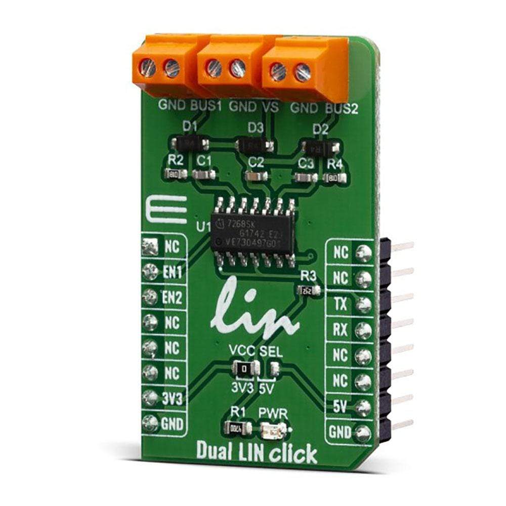
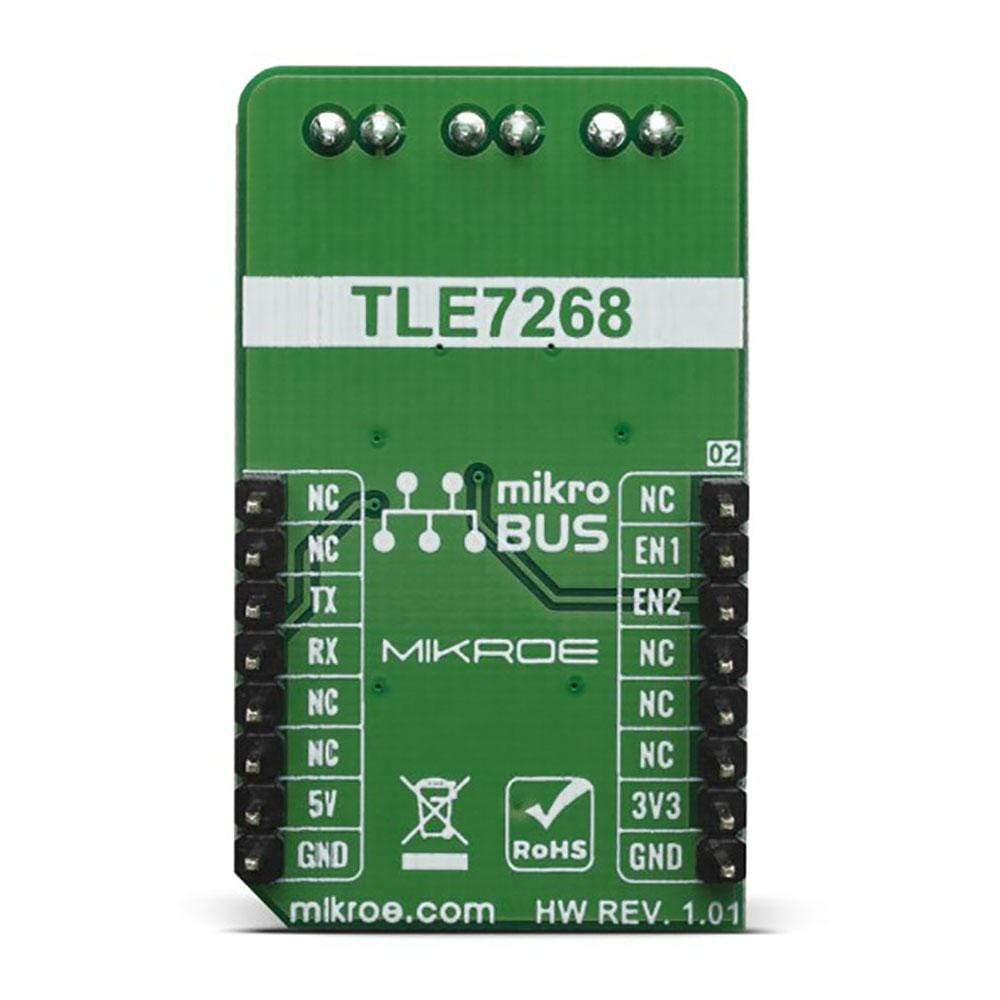
The Dual LIN Click Board™ is based on the Infineon TLE7268SKXUMA1, a Dual LIN transceiver. Given the features included in this transceiver, the Dual LIN transceiver is designed for data transmission rates up to 20 kbps being fully compliant with the ISO17987-4, LIN specification 2.2A and SAE J2602 standards.
Downloads
How Does The Dual LIN Click Board™ Work?
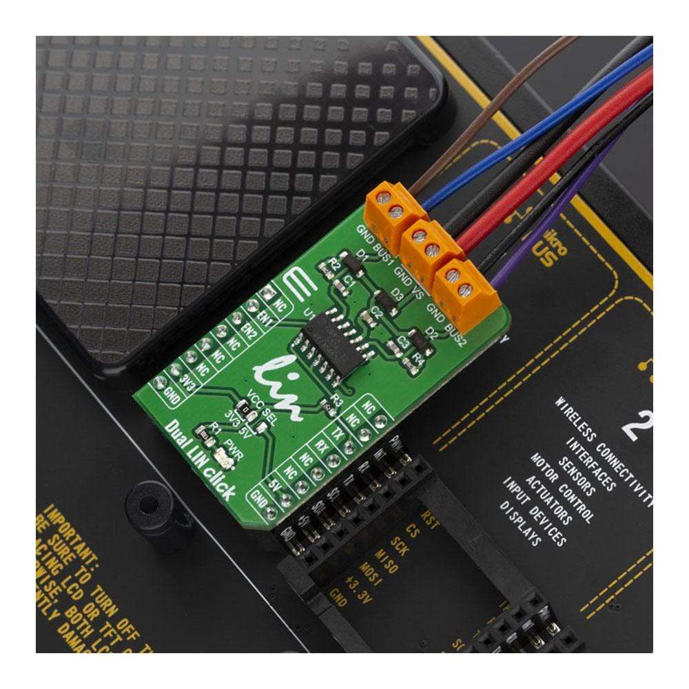
The Dual LIN Click Board™ is a dual transceiver for the Local Interconnect Network (LIN) with integrated wake-up and protection features. The Dual LIN Click Board™ is designed for in-vehicle networks using data transmission rates up to 20 kbps. This Click board™ contains the TLE7268SKXUMA1 from Infineon; Dual LIN Click Board™ includes two independent transceivers that operate as bus drivers between the protocol controller and physical LIN networks.
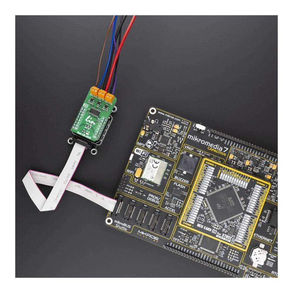
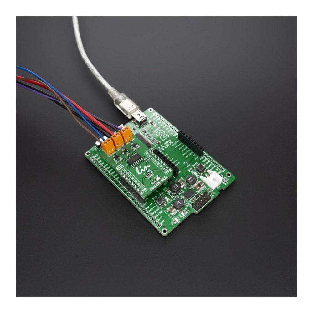
The Dual LIN Click Board™ communicates with the MCU using the UART RX and TX signals. RX and TX signals are also routed to the header on the edge of the Click Board™ board™ so they can be used independently of the mikroBUS™ socket. Its most important features are that it is a two separate single-wire LIN transceiver bus for transmission rates up to 20 kbps and is compliant with ISO 17987-4 and LIN Specification 2.2A.
The EN1 and EN2 pins are used to enable the functionality of BUS 1 or BUS 2 of the device. When the EN1 pin is set to a HIGH logic level, the BUS 1 of the device is set to work in the normal mode, with the transmission paths from TXD to LIN and from LIN to RXD both active.
When the EN2 pin is set to a HIGH logic level, the BUS 2 of the device is set to work in the normal mode, with the transmission paths from TXD to LIN and from LIN to RXD both active. When the EN1 pin is set to a LOW state, the BUS 1 of the device is put into silent mode, depending on the TX pin state. The EN1 pin has a pull-down resistor, so it is pulled to the Ground if left to float. When the EN2 pin is set to a LOW state, the BUS 2 of the device is put into silent mode, depending on the TX pin state. The EN2 pin has a pull-down resistor, so it is pulled to Ground if left to float.
The Dual LIN Click Board™supports different modes of operation of the two transceivers for minimizing ECU current consumption in low power modes, a common INH output can be used for controlling external circuitry, for example, voltage regulators. Based on the Infineon BiCMOS technology. It provides excellent ESD robustness and high electromagnetic compliance (EMC). The TLE7268SKXUMA1 reaches a very low level of electromagnetic emission (EME) within a broad frequency range and is independent of the battery voltage. The TLE7268SKXUMA1 is AEC qualified and tailored to withstand the harsh conditions of the automotive environment.
Some of the key features that are incorporated in the TLE7268SKXUMA1 are overtemperature protection, under-voltage detection. The Dual LIN Click Board™ is digital I/O levels compatible with 3.3 V and 5 V microcontrollers that it is optimized for high electromagnetic compliance (EMC) with very low electromagnetic emission and high immunity to interference. It also features two independent single-wire LIN transceivers in one device and gives out a transmission rate of up to 20 kbps.
Given the features included in this transceiver, the Dual LIN Click Board™ can be used for Body Control Modules (BCM) and Gateway.
SPECIFICATIONS
| Type | LIN |
| Applications | Automotive applications: Body control modules (BCM) and Gateway |
| On-board modules | TLE7268SKXUMA1, a Dual LIN transceiver from Infineon |
| Key Features | Two independent single-wire LIN transceivers in one device, transmission rate up to 20 kbps, very low electromagnetic emission, High immunity to interference |
| Interface | GPIO,UART |
| Compatibility | mikroBUS |
| Click board size | M (42.9 x 25.4 mm) |
| Input Voltage | 3.3V or 5V |
PINOUT DIAGRAM
This table shows how the pinout of the Dual LIN Click Board™ corresponds to the pinout on the mikroBUS™ socket (the latter shown in the two middle columns).
| Notes | Pin | Pin | Notes | ||||
|---|---|---|---|---|---|---|---|
| NC | 1 | AN | PWM | 16 | NC | ||
| Output Enable | EN1 | 2 | RST | INT | 15 | NC | |
| Output Enable | EN2 | 3 | CS | RX | 14 | TX | UART Transmit |
| NC | 4 | SCK | TX | 13 | RX | UART Receive | |
| NC | 5 | MISO | SCL | 12 | NC | ||
| NC | 6 | MOSI | SDA | 11 | NC | ||
| Power Supply | 3.3V | 7 | 3.3V | 5V | 10 | 5V | Power Supply |
| Ground | GND | 8 | GND | GND | 9 | GND | Ground |
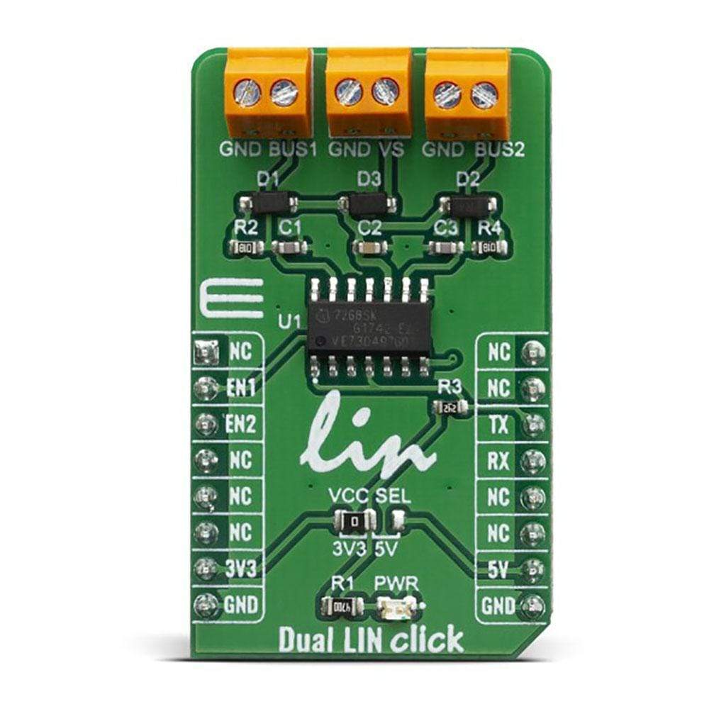
ONBOARD SETTINGS AND INDICATORS
| Label | Name | Default | Description |
|---|---|---|---|
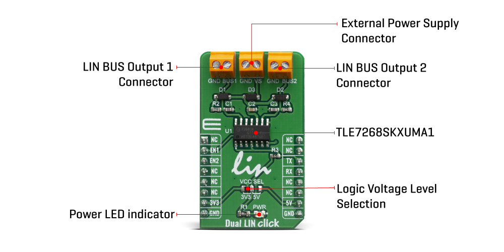
| LD1 | PWR | - | Power LED Indicator |
| TB1 | BUS 1 | - | Terminal block for connecting LIN BUS 1 |
| TB2 | BUS 2 | - | Terminal block for connecting LIN BUS 2 |
| TB2 | VS | - | Terminal block for connecting LIN bus power supply voltage |
| TB2 | VCC SEL | Left | Power supply voltage selection: left position 3.3V, right position 5V |
DUAL LIN CLICK ELECTRICAL SPECIFICATIONS
| Description | Min | Typ | Max | Unit |
|---|---|---|---|---|
| LIN bus supply voltage | 5 | - | 40 | V |
| General Information | |
|---|---|
Part Number (SKU) |
MIKROE-3870
|
Manufacturer |
|
| Physical and Mechanical | |
Weight |
0.019 kg
|
| Other | |
EAN |
8606018719389
|
Frequently Asked Questions
Have a Question?
Be the first to ask a question about this.