


Mikroelektronika d.o.o.
Single Cell Click Board™
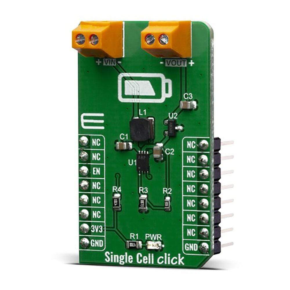
Single Cell Click Board™
SKU: MIKROE-3844
Couldn't load pickup availability
Overview
The Single Cell Click Board™ features MCP16251 synchronous boost regulator with true load disconnect and MCP1811A low-dropout (LDO) linear regulator that provide an ultra low quiescent current during device operation of about 250nA and can be shut down for 5nA (typical) supply current draw. Given the potential applications of these features, the Single Cell Click Board™ can be used for one, two and three-cell Alkaline and NiMH/NiCd portable products, solar cell applications, personal care and medical products, smartphones, MP3 players, wireless sensors and many more.
Downloads
How Does The Single Cell Click Board™ Work?
The Single Cell Click Board™ is based around the MCP16251 from Microchip, a compact, high-efficiency, fixed frequency, synchronous step-up DC-DC converter. This device provides an easy-to-use power supply solution for applications powered by either one-cell, two-cell or three-cell alkaline, NiCd, NiMH, one-cell Li-Ion or Li-Polymer batteries. Low-voltage technology allows the regulator to start-up without high inrush current or output voltage overshoot from a low-voltage input. High efficiency is accomplished by integrating the low-resistance N-Channel boost switch and synchronous P-Channel switch. All compensation and protection circuitry are integrated to minimize external components. MCP16251 is paired with MCP1811A device a good choice for new ultra-long life LDO applications that have high-current demands, but require ultra-low power consumption during sleep periods.
MCP16251 that's featured on Single Cell Click operates and consumes less than 14 µA from battery after start-up, while operating at no load. The device provide a true disconnect from input to output while in shutdown EN = LOW. While in shutdown it consume les than 0.6 µA from battery.
The MCP1811A device is a 150 mA Low-Dropout (LDO) linear regulators that provide high-current and low-output voltages while maintaining an ultra-low 250 nA of quiescent current during device operation. In addition, it can be shut down for 5 nA (typical) supply current draw. The 150 mA output current capability, combined with the low output voltage capability, make the MCP1811A a good choice for new ultra-long life LDO applications that have high-current demands, but require ultra-low power consumption during sleep periods. The MCP1811A device is stable with ceramic output capacitors that inherently provide lower output noise, and reduces the size and cost of the entire regulator solution.
The Single Cell Click Board™ was designed to operate with a wide input voltage range after start-up, down to 0.35V, to accommodate a large variety of input sources. When considering a primary power solution for a design, the battery type and load current needs must be carefully selected. The MCP16251 start-up voltage is typical 0.82V at 1 mA load but this does not act as an UVLO start-up threshold. The device starts draining current to bias its internal circuitry before the 0.82V input and cannot start-up or operate well with high-impedance sources because their voltage varies in time, from zero to over 0.82V (i.e., energy harvesting). Start-up voltage is the point where the device starts switching in closed loop and the output is regulated and depends on load and temperature.
Batteries are available in a variety of sizes and chemistries and can support a variety of drain rates. No matter the chemistry, most batteries have several things in common. They should not be drained below their specified FEP (Functional End Point or Cut-Off Voltage). Below this point, if the battery has a load applied to it, there will not be enough energy to deliver power because all usable capacity is used. For an alkaline cell, FEP is 0.9V or 0.8V. Using the alkaline cell below the FEP will increase the risk of leakage. There is an exception for alkaline batteries: if the battery voltage is strictly monitored, it can be drained down to 0.5V in one-cell applications only. For a rechargeable NiMH cell, the FEP value is usually 1.0V – 1.1V.
Another particular situation is powering a boost circuit from one rechargeable cell like NiMH or NiCd. These applications need an external MCU to monitor the cell voltage or a separate UVLO circuit to prevent deep discharging, which results in permanent cell damage. In a multi-cell powered application (e.g., 2.4V typ. from two NiMH cells) deep discharging will result in a reverse polarity charging of one of the cells due the unbalanced cell voltages, thus damaging the respective cell.
SPECIFICATIONS
| Type | Boost,Linear |
| Applications | Solar cell applications, personal care and medical products, smartphones, MP3 players, wireless sensors and many more |
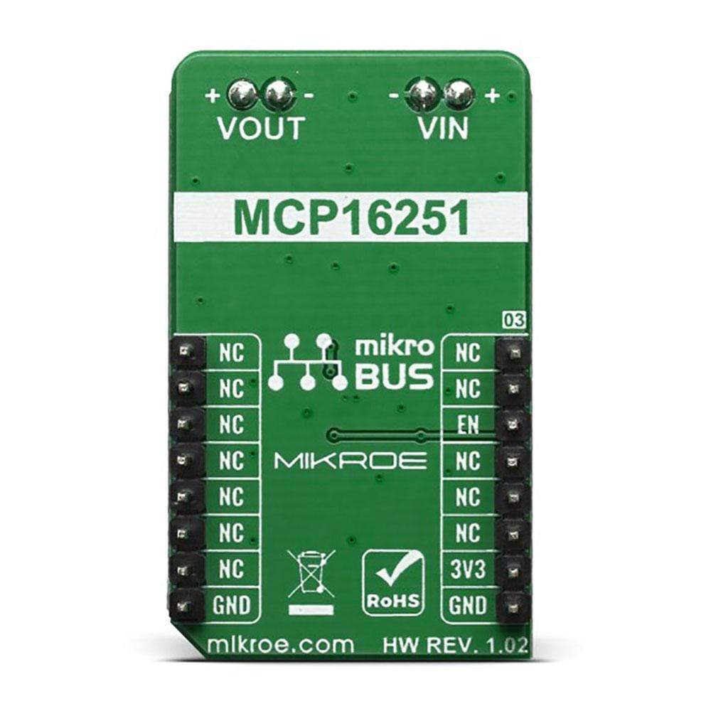
| On-board modules | MCP16251 boost and the MCP1811A LDO |
| Key Features | High-efficiency, Low-voltage input |
| Interface | GPIO |
| Compatibility | mikroBUS |
| Click board size | M (42.9 x 25.4 mm) |
| Input Voltage | 3.3V |
PINOUT DIAGRAM
This table shows how the pinout of the Single Cell Click Board™ corresponds to the pinout on the mikroBUS™ socket (the latter shown in the two middle columns).
| Notes | Pin | Pin | Notes | ||||
|---|---|---|---|---|---|---|---|
| NC | 1 | AN | PWM | 16 | NC | ||
| NC | 2 | RST | INT | 15 | NC | ||
| Enable | EN | 3 | CS | RX | 14 | NC | |
| NC | 4 | SCK | TX | 13 | NC | ||
| NC | 5 | MISO | SCL | 12 | NC | ||
| NC | 6 | MOSI | SDA | 11 | NC | ||
| Power Supply | 3.3V | 7 | 3.3V | 5V | 10 | NC | |
| Ground | GND | 8 | GND | GND | 9 | GND | Ground |
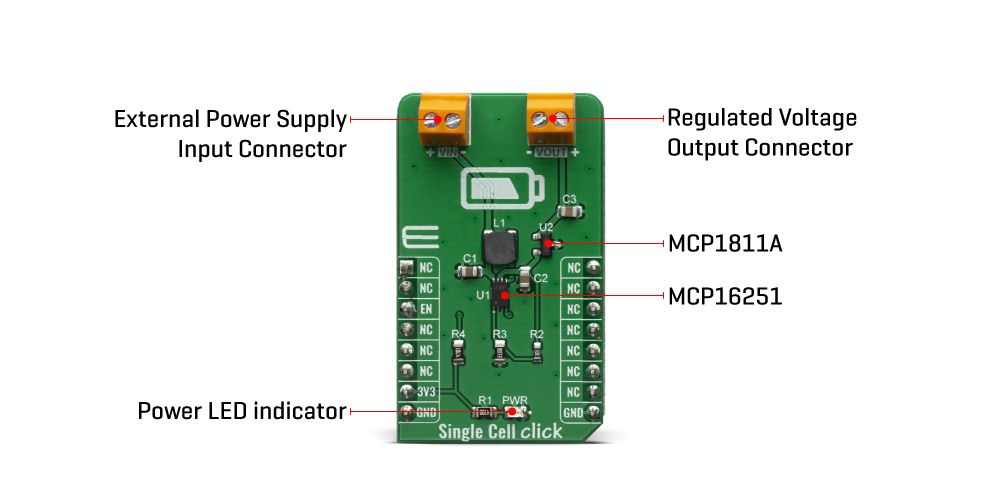
ONBOARD SETTINGS AND INDICATORS
| Label | Name | Default | Description |
|---|---|---|---|
| PWR | LED GREEN | - | Power LED Indicator |
| VIN | - | - | External Power Supply Input Connector |
| VOUT | - | - | Regulated Voltage Output Connector |
| General Information | |
|---|---|
Part Number (SKU) |
MIKROE-3844
|
Manufacturer |
|
| Physical and Mechanical | |
Weight |
0.02 kg
|
| Other | |
EAN |
8606018719532
|
Frequently Asked Questions
Have a Question?
Be the first to ask a question about this.