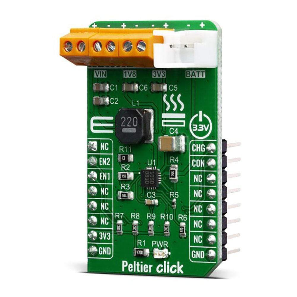
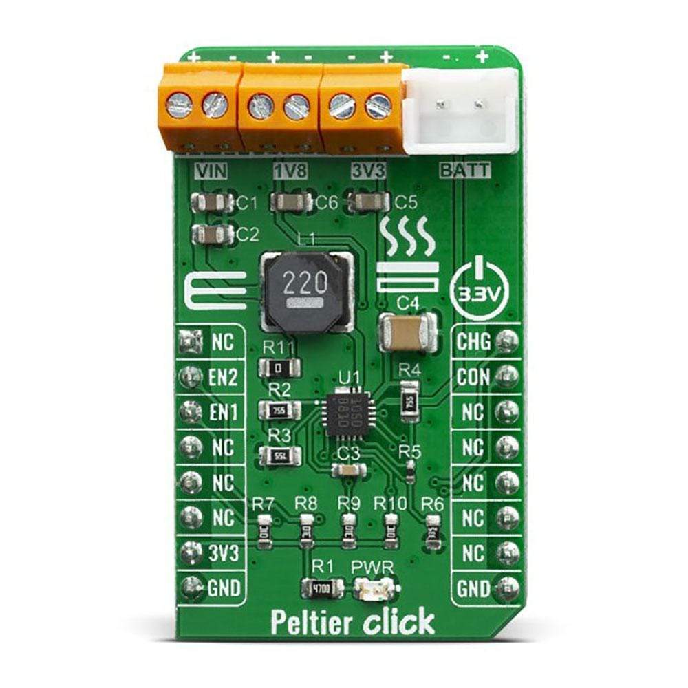
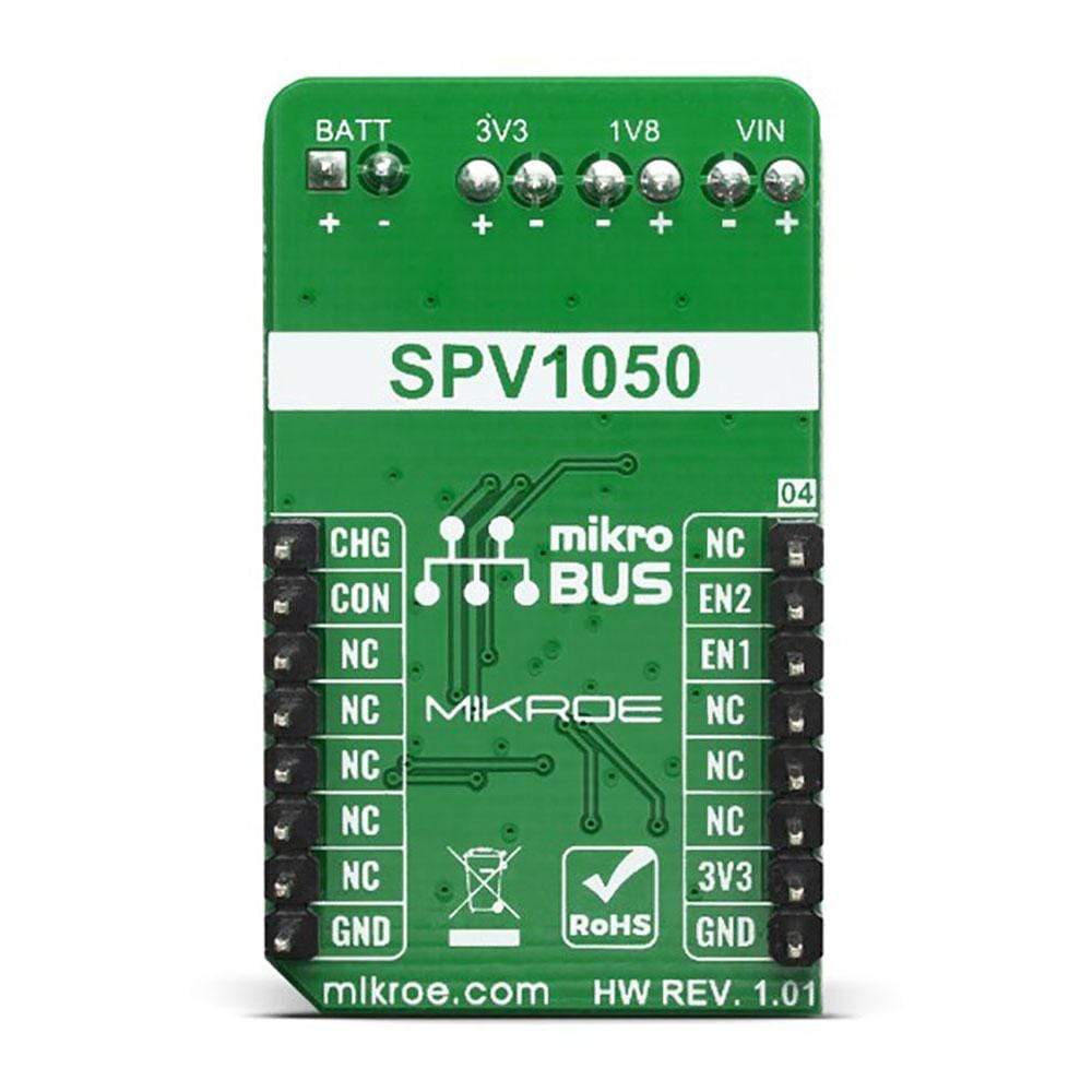
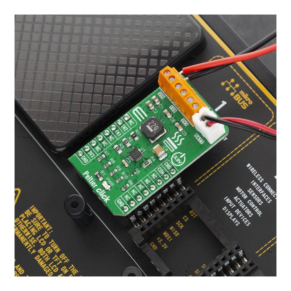
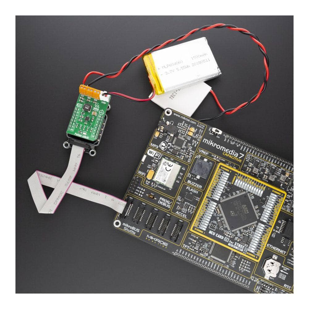
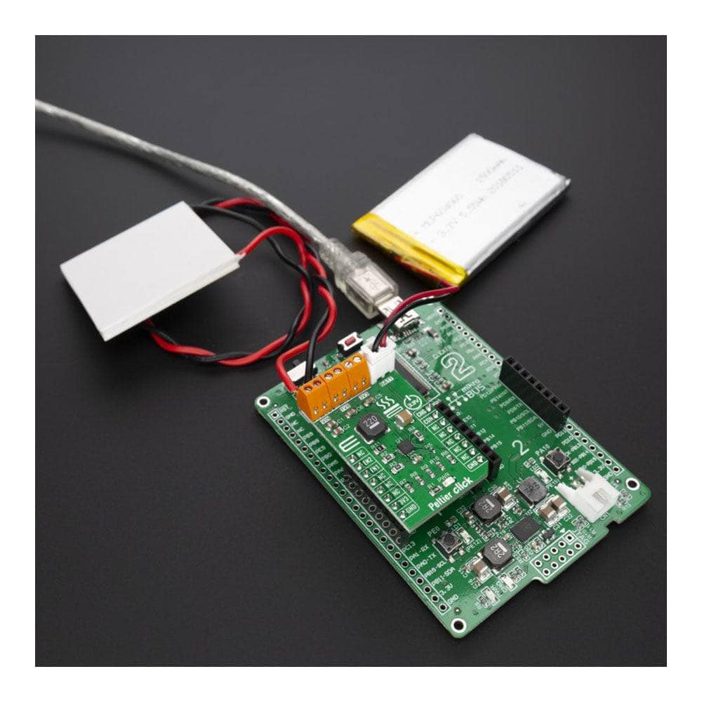
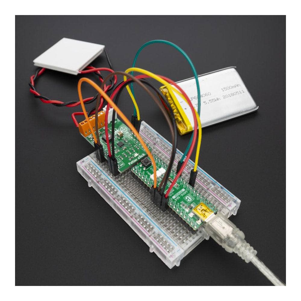
Peltier Click Board
Peltier Click Board
Key Features
- Charge any battery type, including lithium based, solid state thin film and super-capacitor, 3.3v input voltage
- Based on the SPV1050, an ultralow power energy harvester and battery charger from STMicroelectronics
- Variety of applications such as WSN, HVAC, building and home automation, industrial control, remote metering, lighting, security, surveillance, wearable and biomedical sensors and fitness
- mikroBUS: GPIO Interface
Overview
The Peltier Click Board™ uses the SPV1050, an ultralow-power energy harvester and battery charger from STMicroelectronics. The Peltier Click Board™ can charge lithium batteries using a thermoelectric energy harvesting device (TEG). A TEG converts heat directly into electrical energy according to the Seebeck effect. It can be used for various applications such as WSN, HVAC, building and home automation, industrial control, remote metering, lighting, security, surveillance, wearable and biomedical sensors and fitness.
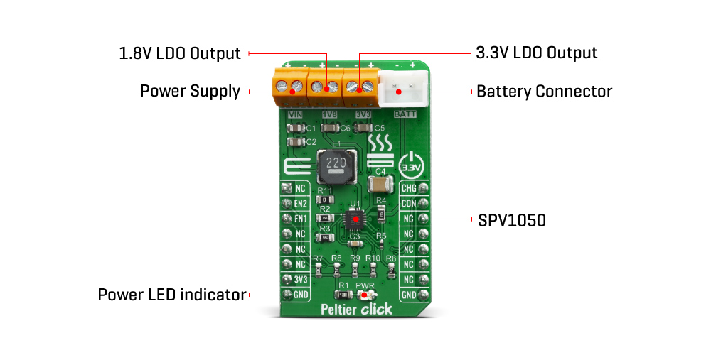
The Peltier Click Board™ is supported by a mikroSDK compliant library, which includes functions that simplify software development. This Click Board™ comes as a thoroughly tested product, ready to be used on a system equipped with the mikroBUS™ socket.
Note: The Peltier Element is available separately.
How Does The Peltier Click Board™ Work?
The Peltier Click Board™ is based on the SPV1050, an ultra-low-power energy harvester and battery charger from STMicroelectronics that can charge lithium based batteries. A thermoelectric harvester produces green energy for energy harvesting with a multitude of advantages: maintenance-free, because of the use of highly reliable and compact solid-state device; silent and quiet; highly efficient in environmental terms because the heat is harvested from waste heat sources and converted into electricity. Because of this feature, the Peltier Click Board™ can be used for a variety of applications such as WSN, HVAC, building and home automation, industrial control, remote metering, lighting, security, surveillance, wearable and biomedical sensors and fitness.
The SPV1050 is an ultralow-power and high efficiency energy harvester and battery charger, which implements the MPPT function and integrates the switching elements of a buck-boost converter. The SPV1050 device allows the charge of lithium battery, by tightly monitoring the end-of-charge and the minimum battery voltage in order to avoid the overdischarge and to preserve the battery life. The power manager is suitable for TEG harvesting sources, as it covers the input voltage range from 75 mV up to 18 V and guarantees high efficiency in both buck-boost and boost configuration.
Furthermore the SPV1050 device shows very high flexibility thanks also to the trimming capability of the end-of-charge and undervoltage protection voltages. In such way any source and battery is matched. The MPPT is programmable by a resistor input divider and allows maximizing the source power under any temperature and irradiance condition.
Some of the key features of the SPV1050 are its transformerless thermoelectric generators and PV modules energy harvester, high efficiency for any harvesting source and it has up to 70 mA maximum battery charging current. It is fully integrated buck-boost DC-DC converter with a programmable MPPT by external resistors, 2.6 V to 5.3 V trimmable battery charge voltage level (± 1% accuracy), 2.2 V to 3.6 V trimmable battery discharge voltage level (± 1% accuracy) with two fully independent LDOs (1.8 V and 3.3 V output). The SPV1050 can enable/disable LDO control pins and it has a battery disconnect function for battery protection, and while the battery is connected and ongoing charge logic open drain indication pins.
The SPV1050 is basically an ultra-low-power energy harvester with an embedded MPPT algorithm, a battery charger and power manager designed for applications up to about 400 mW.
SPECIFICATIONS
Type | Battery charger |
Applications | Variety of applications such as WSN, HVAC, building and home automation, industrial control, remote metering, lighting, security, surveillance, wearable and biomedical sensors and fitness |
On-board modules | SPV1050, an ultralow-power energy harvester and battery charger from STMicroelectronics |
Key Features | Charge any battery type, including lithium based, solid state thin film and super-capacitor, 3.3v input voltage |
Interface | GPIO |
Compatibility | mikroBUS |
Click Board™ size | M (42.9 x 25.4 mm) |
Input Voltage | 3.3V |
PINOUT DIAGRAM
This table shows how the pinout on Peltier Click Board™ corresponds to the pinout on the mikroBUS socket (the latter shown in the two middle columns).
Notes | Pin | Pin | Notes | ||||
---|---|---|---|---|---|---|---|
NC | 1 | AN | PWM | 16 | CHG | Charing | |
Enable 3.3V | EN2 | 2 | RST | INT | 15 | CON | Battery connection |
Enable 1.8V | EN1 | 3 | CS | RX | 14 | NC | |
NC | 4 | SCK | TX | 13 | NC | ||
NC | 5 | MISO | SCL | 12 | NC | ||
NC | 6 | MOSI | SDA | 11 | NC | ||
Power Supply | 3.3V | 7 | 3.3V | 5V | 10 | NC | |
Ground | GND | 8 | GND | GND | 9 | GND | Ground |
ONBOARD SETTINGS AND INDICATORS
Label | Name | Default | Description |
---|---|---|---|
LD1 | PWR | - | Power LED Indicator |
TB1 | VIN | - | Power Supply |
TB2 | 1V8 | - | 1.8V LDO Output |
TB3 | 3V3 | - | 3.3V LDO Output |
J1 | BATT | - | Battery Connector |
PELTIER Click Board™ ELECTRICAL SPECIFICATIONS
Description | Min | Typ | Max | Unit |
---|---|---|---|---|
Maximum battery charging current | - | - | 70 | mA |
BATT pin voltage range | 2.2 | 4.2 | 5.3 | V |
MPPT tracking period | 12 | - | 20 | S |
We provide a library for the Peltier Click Board™ on our LibStock page, as well as a demo application (example), developed using MikroElektronika compilers. The demo can run on all the main MikroElektronika development boards.
Library Description
The library covers all the necessary functions to control the Peltier Click Board™. The Peltier Click Board™ communicates with the target board through the RST, CS, PWM and INT pins. This library offers functions for detecting the states of PWM and INT pins and for seting or clearing RST and CS pins.
Key Functions
void peltier_enableLdo2();
- Function is used to enable 3.3V output.void peltier_enableLdo1();
- Function is used to enable 1.8V output.uint8_t peltier_batteryCharge();
- Function is used to check ongoing battery charge flag pin.
Example Description
The application is composed of three sections :
- System Initialization - Initializes GPIO and LOG structures, sets RST and CS pins as output and PWM and INT pins as input.
- Application Initialization - Initializes GPIO driver, disables both 1.8V and 3.3V outputs and starts write log.
- Application Task - (code snippet) This example demonstrates the use of Peltier Click Board™ by first enableing 1.8V output, second by enableing 3.3V output, then enabling both outputs and finally disabling both outputs in 5 seconds intervals.
void applicationTask() { mikrobus_logWrite( " 1.8V output ", _LOG_LINE ); mikrobus_logWrite( "------------------", _LOG_LINE ); peltier_enableLdo1(); peltier_disableLdo2(); Delay_ms( 5000 ); mikrobus_logWrite( " 3.3V output ", _LOG_LINE ); mikrobus_logWrite( "------------------", _LOG_LINE ); peltier_disableLdo1(); peltier_enableLdo2(); Delay_ms( 5000 ); mikrobus_logWrite( " Both outputs ", _LOG_LINE ); mikrobus_logWrite( "------------------", _LOG_LINE ); peltier_enableLdo1(); peltier_enableLdo2(); Delay_ms( 5000 ); mikrobus_logWrite( " Disable outputs ", _LOG_LINE ); mikrobus_logWrite( "------------------", _LOG_LINE ); peltier_disableLdo1(); peltier_disableLdo2(); Delay_ms( 5000 ); } The full application code, and ready to use projects can be found on our LibStock page.
Other mikroE Libraries used in the example:
- UART
Additional Notes and Information
Depending on the development board you are using, you may need USB UART Click Board™, USB UART 2 Click Board™ or RS232 Click Board™ to connect to your PC, for development systems with no UART to USB interface available on the board. The terminal available in all MikroElektronika compilers, or any other terminal application of your choice, can be used to read the message.
MikroSDK
The Peltier Click Board™ is supported with mikroSDK - MikroElektronika Software Development Kit. To ensure proper operation of mikroSDK compliant Click Board™ demo applications, mikroSDK should be downloaded from the LibStock and installed for the compiler you are using.
Frequently Asked Questions
Have a Question?
Be the first to ask a question about this.