Overview
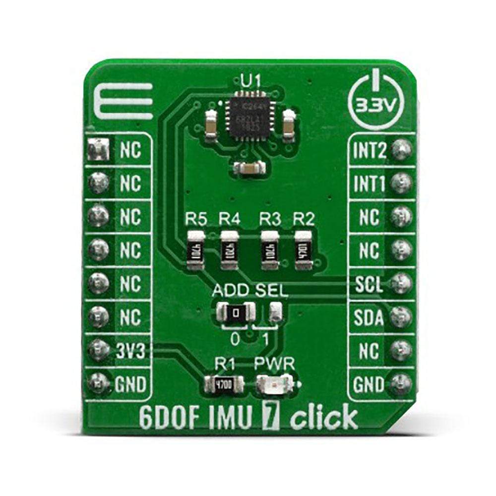
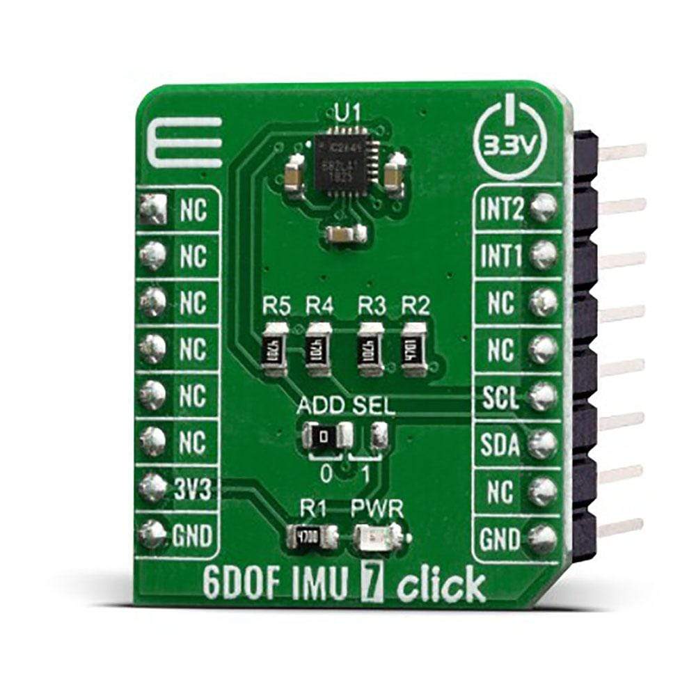
The 6DOF IMU 7 Click Board™ is an advanced 6-axis motion tracking Click Board™, which utilizes the ICM-20649, a high-performance integrated motion sensor, equipped with a 3-axis gyroscope, and a 3-axis accelerometer. There is a MEMS structure hermetically sealed and bonded at the wafer level. Data streams from each axis are fed to a signal processing engine, offering calibrated readings of each axis over the I2C interface. This Click Board™ represents an ideal solution for developing applications in sports, wearable sensors and high impact applications.
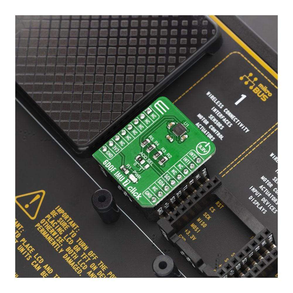
6DOF IMU 7 Click is supported by a mikroSDK compliant library, which includes functions that simplify software development. This Click Board™ comes as a fully tested product, ready to be used on a system equipped with the mikroBUS™ socket.
Downloads
How Does The 6DOF IMU 7 Click Board™ Work?
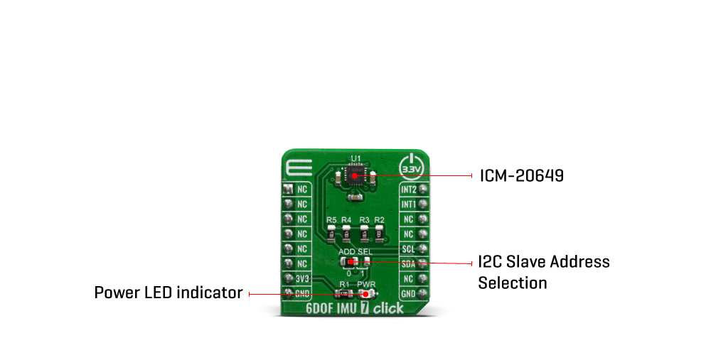
The 6DOF IMU 7 Click Board™ is based on the ICM-20649, a high-performance, 6-axis MEMS MotionTracking™ IC from TDK Invensense. It is an advanced, integrated microelectromechanical gyroscope and accelerometer sensor (MEMS). This allows very high integration and very small dimensions, at an affordable cost. The IC contains a MEMS structure hermetically sealed and bonded at wafer level. The ICM-20649 is the world's first wide-range 6-axis MotionTracking device for Sports and other High Impact applications. It is available in a 3x3x0.9 mm 24-pin QFN package.
Many of today's wearable and sports solutions, which analyze the motion of a user's golf or tennis swings, soccer ball kicks, or basketball activities, require higher than currently available ±2000 dps (degrees per second) FSR for gyroscope and ±16g FSR for accelerometer to better insure that critical data is not lost at the point of high impact or high speed rotation. The ICM-20649 - 6-axis inertial sensor used on the 6DOF IMU 7 Click Board™ offers the smallest size, lowest profile and lowest power in conjunction with industry leading high FSR. With an extended FSR range of ±4000 dps for gyroscope and ±30g for accelerometer, it enables precise analysis of contact sports applications providing continuous motion sensor data before, during and after impact providing more accurate feedback.
ICM-20649 devices, with their 6-axis integration, on-chip DMP, and run-time calibration firmware, enable manufacturers to eliminate the costly and complex selection, qualification, and system level integration of discrete devices, guaranteeing optimal motion performance for consumers. The gyroscope has a programmable full-scale range up to ±4000 dps. The accelerometer has a user-programmable accelerometer full-scale range up to ±30g. Factory-calibrated initial sensitivity of both sensors reduces production-line calibration requirements. Other key features include on-chip 16-bit ADCs, programmable digital filters, an embedded temperature sensor, and programmable interrupts.
The embedded Digital Motion Processor (DMP) within the ICM-20649 offloads computation of motion processing algorithms from the host processor. The DMP acquires data from accelerometers, gyroscopes, and additional third party sensors such as magnetometers, and processes the data. The resulting data can be read from the 512 bytes FIFO that is accessible via the I2C Serial Interface. The FIFO configuration register determines which data is written into the FIFO. The interrupt function may be used to determine when new data is available.
Specifications
| Type | Acceleration,Gyroscope,Motion |
| Applications | It is a perfect solution for development of different types of motion detection and MotionTracking™ applications: sports, wearable sensors and high impact applications |
| On-board modules | ICM-20649, a high-performance, 6-axis MEMS MotionTracking™ IC from TDK Invensense. |
| Key Features | MEMS structure hermetically sealed and bonded at wafer level, 512-byte FIFO buffer enables the applications processor to read the data in bursts • On-Chip 16-bit ADCs and Programmable Filters |
| Interface | I2C |
| Compatibility | mikroBUS |
| Click board size | S (28.6 x 25.4 mm) |
| Input Voltage | 3.3V |
Pinout diagram
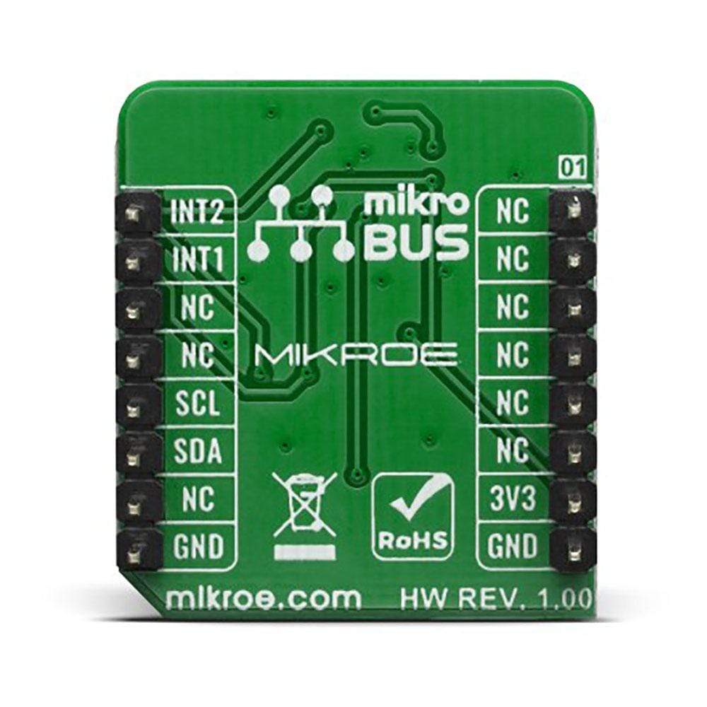
This table shows how the pinout on 6DOF IMU 7 Click Board™ corresponds to the pinout on the mikroBUS™ socket (the latter shown in the two middle columns).
| Notes | Pin |  |
Pin | Notes | |||
|---|---|---|---|---|---|---|---|
| NC | 1 | AN | PWM | 16 | INT2 | External Sync | |
| NC | 2 | RST | INT | 15 | INT1 | Interrupt | |
| NC | 3 | CS | RX | 14 | NC | ||
| NC | 4 | SCK | TX | 13 | NC | ||
| NC | 5 | MISO | SCL | 12 | SCL | I2C Clock | |
| NC | 6 | MOSI | SDA | 11 | SDA | I2C Data | |
| Power Supply | 3.3V | 7 | 3.3V | 5V | 10 | NC | |
| Ground | GND | 8 | GND | GND | 9 | GND | Ground |
Onboard settings and indicators
| Label | Name | Default | Description |
|---|---|---|---|
| LD1 | PWR | - | Power LED Indicator |
| JP1 | ADD SEL | Left | Slave I2C address LSB selection: left position 0, right position 1 |
| General Information | |
|---|---|
Part Number (SKU) |
MIKROE-3776
|
Manufacturer |
|
| Physical and Mechanical | |
Weight |
0.017 kg
|
| Other | |
Country of Origin |
|
HS Code Customs Tariff code
|
|
EAN |
8606018719976
|
Warranty |
|
Frequently Asked Questions
Have a Question?
Be the first to ask a question about this.


