


Mikroelektronika d.o.o.
Charger 13 Click Board™
Charger 13 Click Board™
SKU: MIKROE-3748
Couldn't load pickup availability


Overview
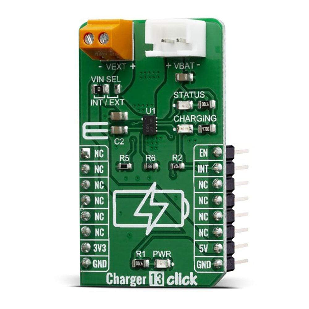
The Charger 13 Click Board™ is a single lithium-ion (Li+) cell battery charger. This click can be used for Low-Cost Li-Ion battery chargers, or Power Tools, toys, backup energy storage solutions, etc. The Charger 13 Click is based on the RT9532GQW battery charger IC, which has some extra features enabling charging without too much hassle. This IC has an internal switching-mode regulation with input current limiting, allowing it to use an external power supply from a cheap wall adapter, rated up to 28V. On the board, there is a Power LED and two extra LED’s which can be used for charging indications.
The Charger 13 Click is supported by a mikroSDK compliant library, which includes functions that simplify software development. This Click Board™ comes as a fully tested product, ready to be used on a system equipped with the mikroBUS™ socket.
Downloads
Charging of the Li+ battery cell is a demanding task that requires a very accurate current and voltage monitoring and limiting. In addition, it also requires specific charging conditions, depending on the battery level (constant current mode, constant voltage mode). Li+ batteries contain flammable chemical compounds and can easily be ignited. The RT9532GQW IC closely monitors the battery voltage and current during the charging process, ensuring safe and reliable operation. The Charger 13 Click Board™ is a perfect solution for the development of multiple Li+ battery cell charging applications, offering a set of connectors, pins, and LED indicators, allowing fast and easy prototyping.
How Does The Charger 13 Click Board™ Work?
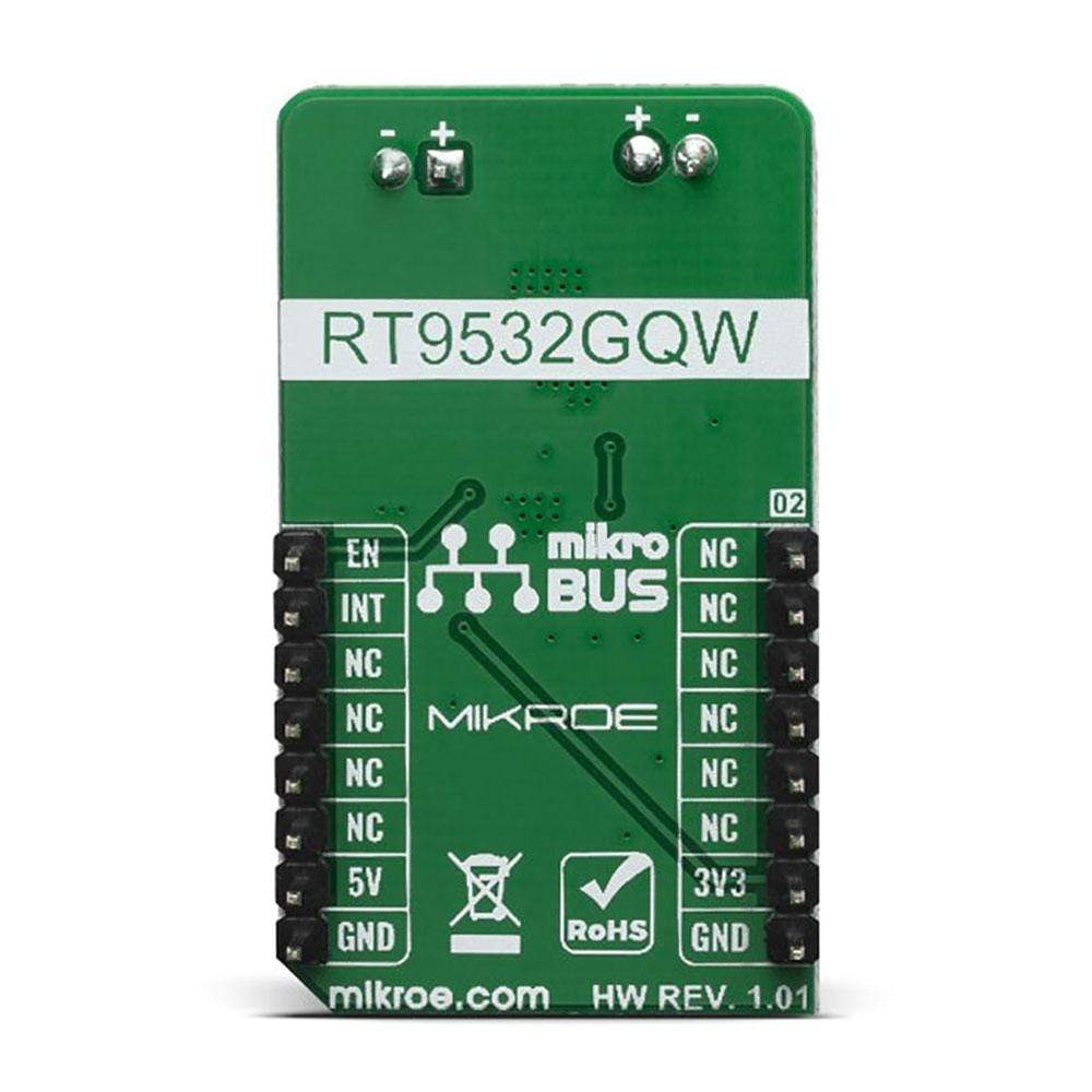
The Charger 13 Click Board™ is based on the RT9532GQW - fully integrated single cell Li-ion battery charger IC ideal for portable applications. The RT9532 optimizes the charging task by using a control algorithm including pre-charge mode, fast charge mode and constant voltage mode. The input voltage range of the VIN pin can be as high as 28V. When the input voltage exceeds the OVP threshold, it will turn off the charging MOSFET to avoid overheating of the chip. Along with its small physical size, the low number of external components makes this IC ideally suitable for various applications. The 4.2V factory preset reference voltage simplifies design.
.jpg)
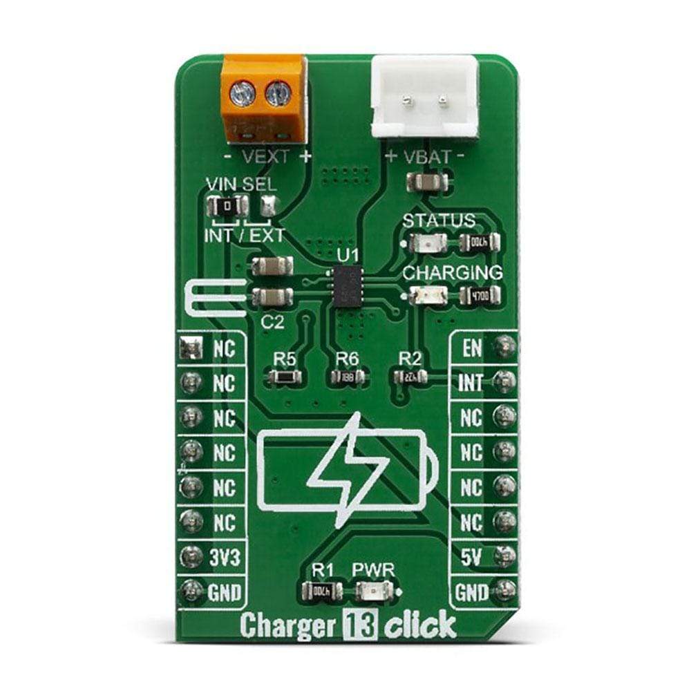
The RT9532GQW IC is designed with reliability in mind: the IC prevents draining the battery below the critical level, offers prequel charging (for deeply depleted batteries), features an overvoltage protection, charging status monitoring and so on. The Charger 13 Click Board™ itself is equipped with a set of indicators used to monitor both charging process and power distribution.
- CHARGE LED indicates the charge-in-progress status.
- STATUS LED indicates power status during the charging process.
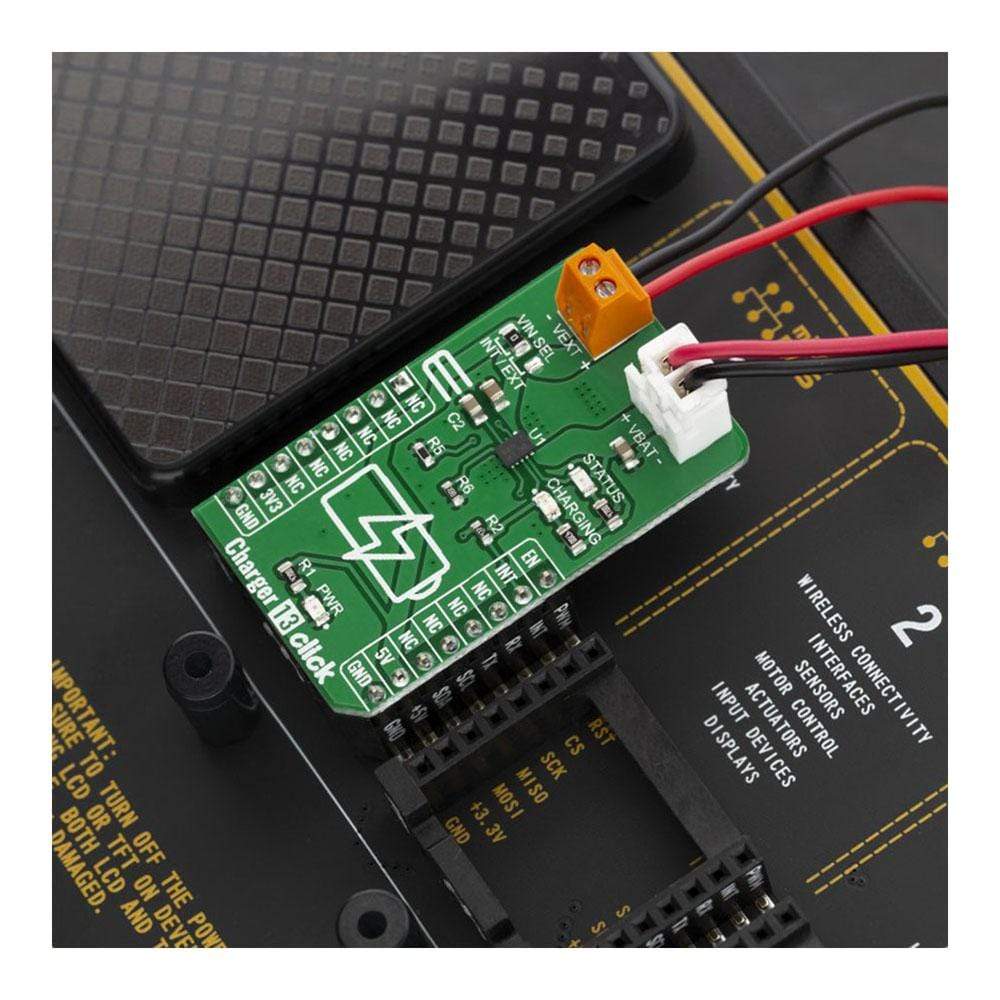
On the left side of the click board is an input screw terminal with corresponding markings, where the external voltage as high as 28V can be applied. The connector on the right side is reserved for a Li-Ion battery with GND and VBAT+ markings. When connected to power source, the green STATUS LED will indicate it, while the red – CHARGING LED will indicate the charging in progress and will turn off once the battery charging is finished.
The voltage range which can be used to power up the Charger 13 Click Board™, allows for it to work with both 3.3V and 5V capable MCUs. It can be selected by soldering a small SMD jumper, labeled as VCC SEL to the correct position.
SPECIFICATIONS
| Type | Battery charger |
| Applications | The Charger 13 Click Board™ is a perfect choice for development lithium-ion (Li+) cell battery charging applications. |
| On-board modules | RT9532GQW, a highly Integrated, linear battery charger from Richtek |
| Key Features | Intelligent, constant-current, constant voltage (CCCV), temperature-regulated battery charger |
| Interface | GPIO |
| Compatibility | mikroBUS |
| Click board size | M (42.9 x 25.4 mm) |
| Input Voltage | 3.3V,5V |
PINOUT DIAGRAM
This table shows how the pinout on the Charger 13 Click Board™ corresponds to the pinout of the mikroBUS™ socket (the latter shown in the two middle columns).
| Notes | Pin | Pin | Notes | ||||
|---|---|---|---|---|---|---|---|
| NC | 1 | AN | PWM | 16 | EN | Enable In | |
| NC | 2 | RST | INT | 15 | INT | Charging Interrupt Out | |
| NC | 3 | CS | RX | 14 | NC | ||
| NC | 4 | SCK | TX | 13 | NC | ||
| NC | 5 | MISO | SCL | 12 | NC | ||
| NC | 6 | MOSI | SDA | 11 | NC | ||
| Power Supply | 3.3V | 7 | 3.3V | 5V | 10 | 5V | Power Supply |
| Ground | GND | 8 | GND | GND | 9 | GND | Ground |
ONBOARD SETTINGS AND INDICATORS
| Designator | Name | Default Position | Default Options | Description |
|---|---|---|---|---|
| JP1 | VIN SEL | Left | 5V | Power Supply Selection Jumper INT/EXT, left position INT, right position EXT |
| LD1 | STATUS | - | - | Power Status LED indicator |
| LD2 | CHARGING | - | - | Charging Status LED indicator |
| LD3 | PWR | - | - | Power LED Indicator |
| General Information | |
|---|---|
Part Number (SKU) |
MIKROE-3748
|
Manufacturer |
|
| Physical and Mechanical | |
Weight |
0.018 kg
|
| Other | |
EAN |
8606018716951
|
Frequently Asked Questions
Have a Question?
Be the first to ask a question about this.