


Mikroelektronika d.o.o.
Joystick 2 Click Board™
Joystick 2 Click Board™
SKU: MIKROE-3711
Couldn't load pickup availability
Overview
The Joystick 2 Click Board™ is a smart navigation key concept based on SKRHABE010 by Alps, a 4-direction joystick switch with Center-push Function. Alps switches, also known as microswitches, are well renowned for their reliability and endurance. Joystick switches of this kind are widely used in many different applications. Joystick 2 click can be used in numerous different applications, as a human-machine interface device (HMI), such as cell phones, tablets, terminals, video games, toys, and many more.
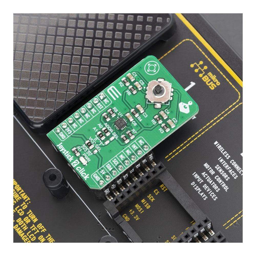
The Joystick 2 Click Board™ is supported by a mikroSDK compliant library, which includes functions that simplify software development. This Click Board™ comes as a fully tested product, ready to be used on a system equipped with the mikroBUS™ socket.
Downloads
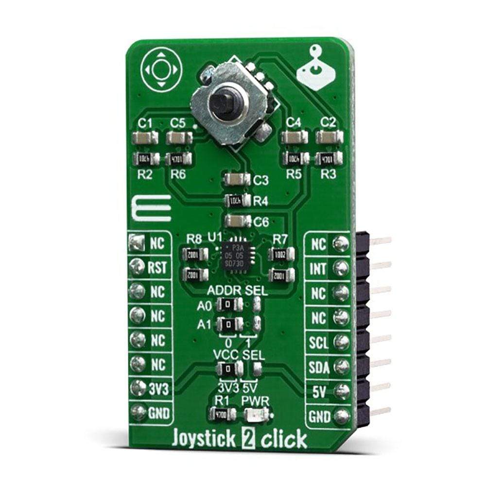
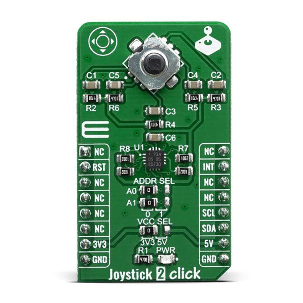
The Joystick 2 Click Board™ includes the SKRHABE010 by Alps, which is the omni directional joystick switch with center-push function. The mentioned joystick switch have 5 output pins – each for a single switch direction. With its body height of 1.85mm, it is very easy to implement it in various designs and thanks to the simple principles of operation, users have the ability to adapt it in a desired way. Its long-life (of 1 million life cycles) guarantees the rigidity and durability of the product.
How Does The Joystick 2 Click Board™ Work?
The Joystick 2 Click Board™ contains a SKRHABE01, a 4-direction joystick switch with Center-push Function by Alps. It is positioned on the board so it is easily accessible for interacting and the lever could be pressed, activating the microswitch that way. The microswitch is actuated by applying very little physical force, using a tipping-point mechanism which results in fast and reliable snap-in action. It has both NO (Normal open) contacts routed to the mikroBUS™ over the port expander. The switch lines are equipped with the RC filters, which serve as debouncing elements for the switch and also to pull-up the lines when they are left afloat. This way, the contact bouncing is reduced even further, resulting in an accurate detection of the switching event.
.jpg)
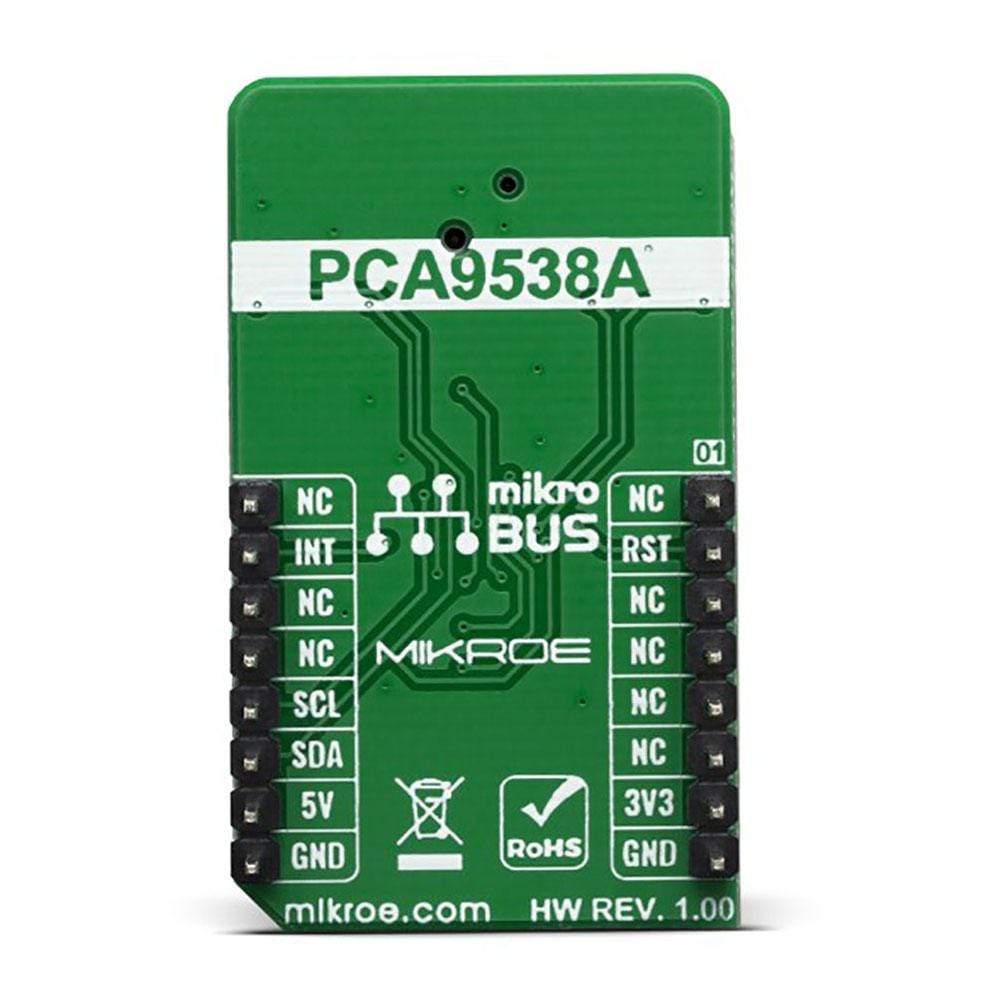
As already mentioned above, this click board™ contains the port expander, relatively large number of needed GPIO pins for the joystick switch. Used IC is PCA9538A, Low-voltage 8-bit I2C-bus I/O port with interrupt and reset, from NXP Semiconductors. It uses the I2C communication for interfacing with the main MCU, which simplifies the number of needed pins, and therefore the design itself. The Active LOW reset input (RESET) and Open-drain active LOW interrupt output (INT) pins helps simplifying the design even further.
The Joystick 2 Click Board™ also features an onboard jumper selector, which is used to select the voltage level that is connected to the microswitch input pin, making it usable for both 3V3 and 5V capable microcontoller pins.
SPECIFICATIONS
| Type | Pushbutton/Switches |
| Applications | Cell phones, tablets, terminals, video games, toys, and many more. |
| On-board modules | SKRHABE010 4-direction joystick switch with Center-push Function by Alps and Port Expander IC from NXP, PCA9538A |
| Key Features | High-quality microswitch, high mechanical and electrical durability, debouncing features |
| Interface | GPIO,I2C |
| Compatibility | mikroBUS |
| Click board size | M (42.9 x 25.4 mm) |
| Input Voltage | 3.3V or 5V |
PINOUT DIAGRAM
This table shows how the pinout of the Joystick 2 Click Board™ corresponds to the pinout on the mikroBUS™ socket (the latter shown in the two middle columns).
| Notes | Pin | Pin | Notes | ||||
|---|---|---|---|---|---|---|---|
| NC | 1 | AN | PWM | 16 | NC | ||
| Reset IN | RST | 2 | RST | INT | 15 | INT | Interrupt Out |
| NC | 3 | CS | RX | 14 | NC | ||
| NC | 4 | SCK | TX | 13 | NC | ||
| NC | 5 | MISO | SCL | 12 | SCL | I2C Clock | |
| NC | 6 | MOSI | SDA | 11 | SDA | I2C Data | |
| Power Supply | 3.3V | 7 | 3.3V | 5V | 10 | 5V | Power supply |
| Ground | GND | 8 | GND | GND | 9 | GND | Ground |
ONBOARD SETTINGS AND INDICATORS
| Label | Name | Default | Description |
|---|---|---|---|
| JP1 | VCC SEL | Left | Power supply voltage selection. Left position 3V3, right position 5V |
| LD1 | Power LED | - | Power LED indicates that the click is powered on |
| JS1 | SWITCH | - | Onboard switch |
JOYSTICK 2 CLICK ELECTRICAL SPECIFICATIONS
| Description | Min | Typ | Max | Unit |
|---|---|---|---|---|
| Contact resistance | - | - | 100 | mΩ |
| Mechanical durability (30 operations/min) | - | - | 1 milion | cycles |
| General Information | |
|---|---|
Part Number (SKU) |
MIKROE-3711
|
Manufacturer |
|
| Physical and Mechanical | |
Weight |
0.019 kg
|
| Other | |
EAN |
8606018716692
|
Frequently Asked Questions
Have a Question?
Be the first to ask a question about this.