
Mikroelektronika d.o.o.
Thermo 11 Click Board™
Thermo 11 Click Board™
SKU: MIKROE-3600
Couldn't load pickup availability


Overview
The Thermo 11 Click Board™ is a Click Board™ equipped with the sensor IC, which can digitize temperature measurements between -55°C and +150°C so that the host MCU can process the temperature measurement data. The Thermo 11 Click Board™ provides an accuracy of ±0.1°C in the range from -20°C to +50°C.
The sensor used on this Click Board™ has a great combination of features that make it a perfect choice for any temperature measurement application: low power consumption, Selectable averaging, programmable interrupt engine, compact sensor size, interrupt output pin, and more. The sensor itself requires almost no external components, which simplifies the design, reducing the cost and cutting the time to market.
Downloads
The Thermo 11 Click Board™ is specially designed so it retains the specified characteristics of the sensor IC. Equipped with this sophisticated, accurate and simple to use sensor IC, it can be used for measuring and monitoring the temperature in a whole range of applications, such as the PC case and other internal components temperature monitoring, office equipment and entertainment systems thermal monitoring, general purpose thermal measurement, and similar digital thermal measurement applications, that require a precise thermal measurement and an overtemperature alert.
How Does The Thermo 11 Click Board™ Work?
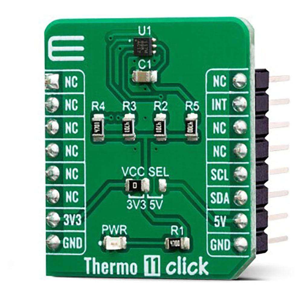
The active temperature sensing component on the Thermo 11 Click Board™ is the TMP117, a high accuracy temperature sensor IC with the 2-Wire interface, from Texas Instruments. The Click Board™ itself has a reasonably small number of components because most of the measurement circuitry is already integrated on the TMP117 sensor. The I2C / SMBus compatible serial interface lines, along with the INT pin, which also works in the open drain configuration, are pulled up by the onboard resistors. The 2-Wire lines are routed to the respective I2C lines of the mikroBUS (SCK and SDA), while the INT pin is routed to the INT pin of the mikroBUS.
The sensor IC uses the I2C/SMBus compatible communication interface. There are ten registers, used to set the high and low temperature limits, temperature hysteresis for the interrupt events, configuration register used to store all the working parameters, read-only register which holds the sampled temperature data, and more. More information about all the registers can be found in the TMP117 datasheet. However, provided library contains functions that simplify the use of the Thermo 11 Click Board™. The included application example demonstrates their functionality and it can be used as a reference for custom design.
An analog signal from the thermal sensor is sampled by the internal ADC converter, with the resolution of 16 bits. Thanks to high resolution ADC, the step size can be as small as 0.0078°C, depending of the measuring temperature range. Users can configure the device to report the average of multiple temperature conversions with to reduce noise in the conversion results. The device accumulates those conversion results and reports the average of all the collected results at the end of the process. The INT pin is used to trigger an interrupt event on the host MCU. This pin has a programmable polarity: it can be set to be asserted either to a HIGH logic level or to a LOW logic level by setting POL bit in the configuration register. Since the Click Board™ features a pull-up resistor, it is advised to set the polarity so that the asserted state drives the pin to a LOW logic level. A special mechanism is employed to reduce false ALERT triggering. This mechanism includes queueing of the cycles in which the temperature limit is exceeded The ALERT pin can be set to work in two different modes: Comparator mode and therm mode.
When working in the Comparator mode, this pin will be triggered whenever a temperature limit is exceeded. The INT pin stays asserted until the temperature drops below the hysteresis level. Both values are set in the respective temperature registers (limit and hysteresis). This mode is useful for thermostat-like applications: it can be used to power down a system in case of overheating or turn off the cooling fan if the temperature is low enough.
If set to work in the therm mode, the INT pin will stay asserted when the temperature exceeds the value in the high limit register. When the temperature drops below the hysteresis level, the INT pin will be cleared. This mode is used to trigger an interrupt on the host MCU, which is supposed to read the sensor when the interrupt event is generated.
The device can be set to work in several different power modes. It can be set to continuously sample the temperature measurements, it can be set to work in the one-shot mode, and it can be set to stay in the shutdown mode. The shutdown mode consumes the least power, keeping all the internal sections but the communication section, unpowered. The one-shot mode allows the device to stay in the shutdown mode, run a single conversion cycle on demand, and the revert back to the shutdown mode. This allows for a lower power consumption. The design of the Click Board™ itself is such that the thermal radiation from other components, which might affect the environmental temperature readings of the sensor, is reduced. The onboard SMD jumper labelled as VCC SEL allows voltage selection for interfacing with both 3.3V and 5V MCUs.
SPECIFICATIONS
| Type | Temperature & humidity |
| Applications | It can be used for the PC case temperature monitoring, office equipment, and entertainment systems thermal monitoring, general purpose thermal measurement, etc. |
| On-board modules | TMP117, a high accuracy temperature sensor IC with the 2-Wire interface, from Texas Instruments |
| Key Features | low-power consumption, Selectable averaging, programmable interrupt engine, compact sensor size, interrupt output pin |
| Interface | I2C |
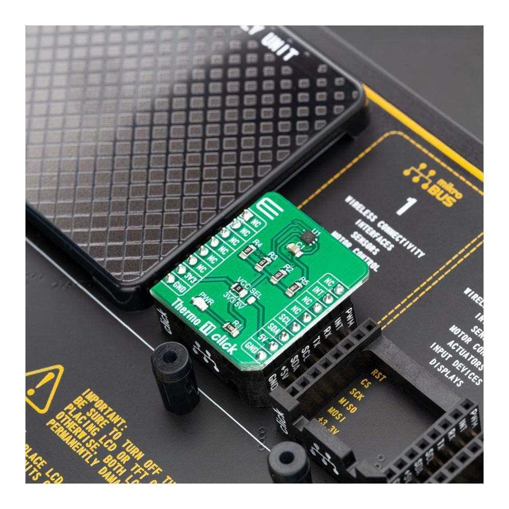
| Compatibility | mikroBUS |
| Click Board™ size | S (28.6 x 25.4 mm) |
| Input Voltage | 3.3V or 5V |
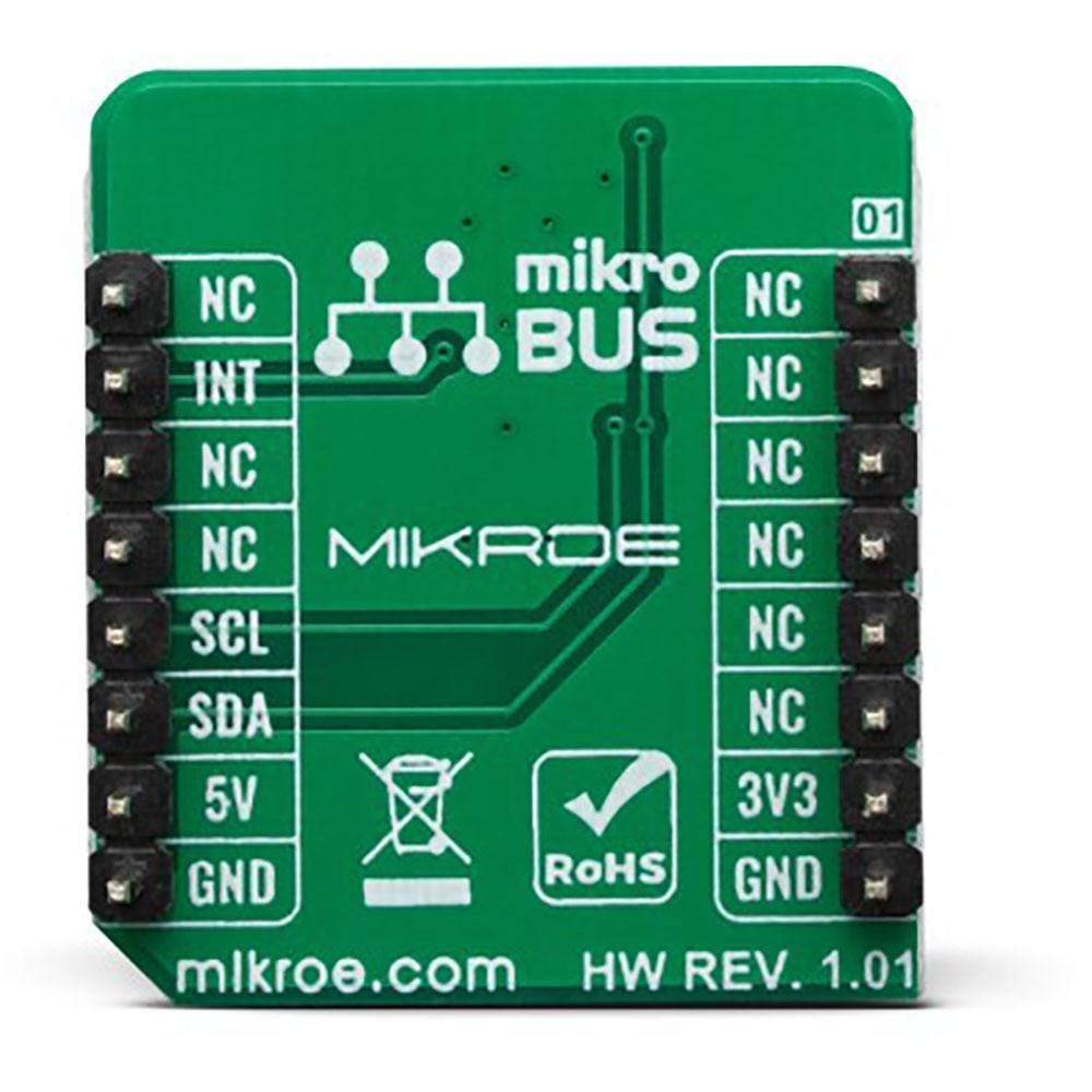
PINOUT DIAGRAM
This table shows how the pinout on Thermo 11 Click Board™ corresponds to the pinout on the mikroBUS socket (the latter shown in the two middle columns).
| Notes | Pin | Pin | Notes | ||||
|---|---|---|---|---|---|---|---|
| NC | 1 | AN | PWM | 16 | NC | ||
| NC | 2 | RST | INT | 15 | INT | Interrupt output | |
| NC | 3 | CS | RX | 14 | NC | ||
| NC | 4 | SCK | TX | 13 | NC | ||
| NC | 5 | MISO | SCL | 12 | SCL | I2C Clock | |
| NC | 6 | MOSI | SDA | 11 | SDA | I2C Data | |
| Power Supply | +3.3V | 7 | 3.3V | 5V | 10 | +5V | Power Supply |
| Ground | GND | 8 | GND | GND | 9 | GND | Ground |
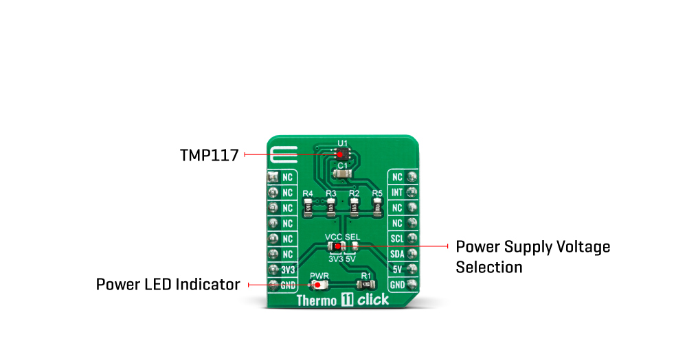
ONBOARD SETTINGS AND INDICATORS
| Label | Name | Default | Description |
|---|---|---|---|
| JP1 | VCC SEL | Left | Power supply voltage selection: left position 3V3, right position 5V |
| LD1 | PWR | - | Power LED indicator |
THERMO 11 Click Board™ MAXIMUM RATINGS
| Description | Min | Typ | Max | Unit |
|---|---|---|---|---|
| Temperature Range (accuracy ±0.3˚C) | -55 | - | +150 | °C |
| Temperature Range (accuracy ±0.1˚C) | -20 | - | +50 | °C |
| Communication speed | 0 | - | 400 | kHz |
| Conversion time | 13 | 15.5 | 17.5 | ms |
| General Information | |
|---|---|
Part Number (SKU) |
MIKROE-3600
|
Manufacturer |
|
| Physical and Mechanical | |
Weight |
0.018 kg
|
| Other | |
EAN |
8606018716012
|
Frequently Asked Questions
Have a Question?
Be the first to ask a question about this.