


Mikroelektronika d.o.o.
Light Temp Click Board™
Light Temp Click Board™
SKU: MIKROE-3399
Couldn't load pickup availability


Overview
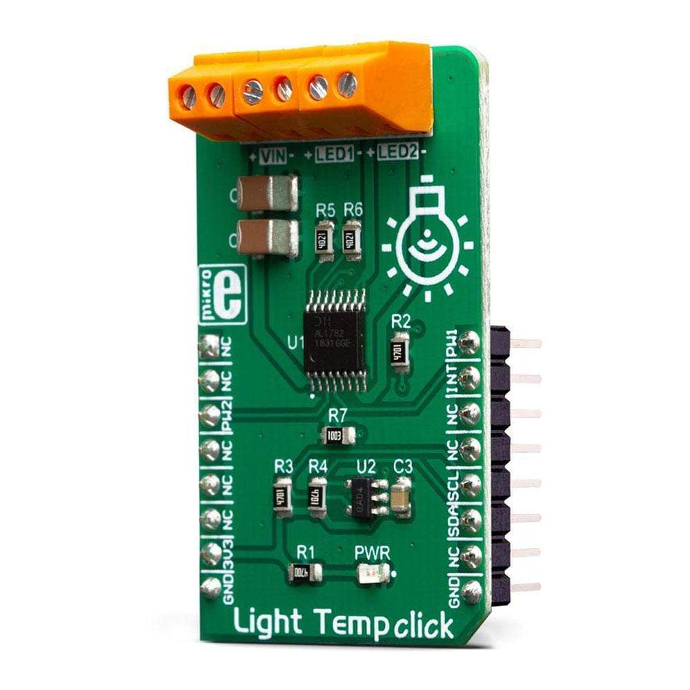
The Light Temp Click Board™ is a dual-channel LED driver, designed to be used in tunable Smart Connected Lighting (SCL) applications. It is based on the AL1782, a dual-channel PWM dimmable linear LED driver. By utilizing a high-frequency E-flicker free technology with Deep Dimming capability, it can be used in both single-channel dimmable white and dual-channel tunable white SCL applications.
The AL1782 IC features the Adaptive Thermal Management scheme, reducing power dissipation. It also integrates an abundance of protection features for increased reliability: under-voltage, open or short circuit at the output, and thermal protection.
Downloads
The AL1782 integrates two low-side current sinks which allow LED strips or LED bulbs to be connected in the common-anode topology for increased effectiveness and power optimization. This IC is designed with the power optimization in mind whenever there is no valid PWM signal on its input pins, it enters the low-power mode, preventing unnecessary power dissipation. An additional ADC IC is used, allowing advanced power optimization. Offering good reliability, linear dimming response, and low power consumption, the Light Temp Click Board™ is a perfect solution for smart lighting applications, SCL LED bulbs, but also for driving LED strips and high-power LEDs.
How Does The Light Temp Click Board™ Work?
The Light Temp Click Board™ is based on the AL1782, a dual-channel PWM dimmable linear LED driver by Diodes Incorporated. It is a constant-current driver, which can sink up to 1500mA combined, or up to 750mA per channel. It has two low-side current sinks which allow LED strips or LED bulbs to be connected in the common-anode topology for increased effectiveness and power optimization. Note that the constant current on this Click board™ is set to 750mA per channel.
The AL1782 IC can be operated with a PWM signal in the frequency range from 1kHz to 40kHz. By applying the PWM signal with the duty cycle of less than 4ms, it is possible to tune the light intensity of the connected LED light element. A LOW pulse width of more than 4ms will set the device into the low-power mode (suspend). The lowest light intensity that can be reached by applying the PWM frequency of 1kHz is 0.1%, while 40kHz allows the lowest brightness level of 4% of the full light intensity. A High PWM frequency allows for less visible flickering, but limits the lowest light intensity level, at the same time. PWM1 and PWM2 pins of the AL1782 are routed to the mikroBUS™ PWM and CS pins and are labelled as PW1 and PW2.
Adaptive Thermal Management (ATM) scheme is one of the key features of the AL1782. It can be used to optimize the power consumption by adjusting the voltage of the external power supply unit (PSU): the excessive voltage applied to the connected LED will be dissipated as heat within the AL1782 IC. Therefore, the voltage level of the external PSU should be kept above the forward voltage of the connected LED plus minimum voltage headroom (VF + VLED_REG). The ATM injects current through the LEDPG pin of the AL1782. This current is converted to a voltage level, and it is sampled by the MCP3221, a low-power 12-bit A/D converter with I2C interface, by Microchip. It has its I2C pins routed to the respective mikroBUS™ I2C pins, allowing the host MCU to read the LEDPG voltage and make PSU voltage adjustments. Please note that if an external PSU with no external regulation is used, its voltage should stay within the mentioned range (VF of the connected LED element + VLEDx_REG as per AL1782 datasheet). However, the voltage should always stay below 30V.
The AL1782 IC also integrates an abundance of protection features for increased reliability: undervoltage, open or short circuit at the output, and thermal protection. If any of these protections become activated, a fault event will be reported on a dedicated pin, labelled as FAULTB. This pin is routed to the mikroBUS™ INT pin and it is asserted to a LOW logic level when a fault event occurs.
Deep Dimming Capability helps with power efficiency. Subjective perception of the light intensity differs from the measured light. For example, the light intensity of 10% (in respect to the applied duty cycle) is perceived as 32% of the full light intensity. Deep Dimming Capability helps with energy saving, providing an optimal light output. Deep Dimming down to 0.1% is possible with the AL1782 IC, since it can be operated with the pulse width as low as 1 µS, while still providing good linearity.
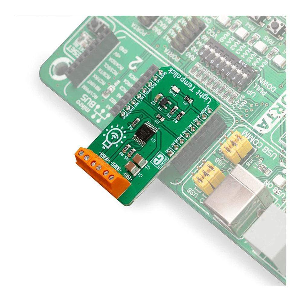
The Light Temp Click Board™ is designed to be used along with an external PSU and an MCU. The full potential of the Light Temp click is achieved when combined with a dedicated light temperature and color sensing Click board™ such as Spectral click: by receiving information about the ambient light color temperature and white balance from the Spectral click, the MCU can generate PWM signal in respect to the required CCT tuning and send it to Light Temp click to regulate the color of the ambient lighting.
The Light Temp Click Board™ is designed to be operated by 3.3V logic levels only. A proper logic voltage level translation should be performed before the Click board™ is used MCUs which are operated at 5V.
SPECIFICATIONS
| Type | LED Drivers |
| Applications | The Light Temp Click Board™ is a perfect solution for smart lighting applications, SCL LED bulbs, but also for driving LED strips and high-power LEDs. |
| On-board modules | AL1782, a dual-channel PWM dimmable linear LED driver by Diodes Incorporated; MCP3221, a low-power 12-bit A/D converter with I2C interface, by Microchip. |
| Key Features | Many protection features for increased reliability: undervoltage, open or short circuit at the output, thermal protection… High-frequency E-flicker free technology with Deep Dimming capability, Adaptive Thermal Management scheme, etc. |
| Interface | I2C,PWM |
| Compatibility | mikroBUS |
| Click board size | M (42.9 x 25.4 mm) |
| Input Voltage | 3.3V |
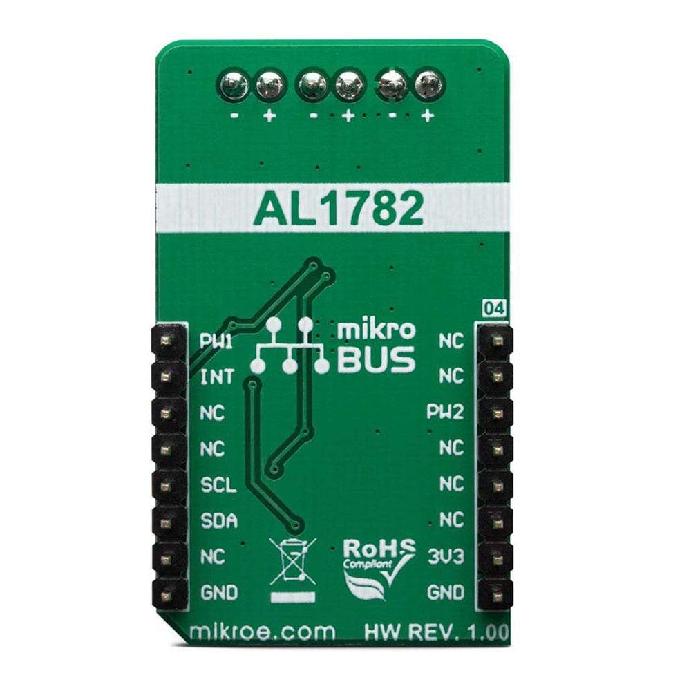
PINOUT DIAGRAM
This table shows how the pinout of the Light Temp Click Board™ corresponds to the pinout on the mikroBUS™ socket (the latter shown in the two middle columns).
| Notes | Pin | Pin | Notes | ||||
|---|---|---|---|---|---|---|---|
| NC | 1 | AN | PWM | 16 | PW1 | PWM Input 1 | |
| NC | 2 | RST | INT | 15 | INT | Fault status | |
| PWM Input 2 | PW2 | 3 | CS | RX | 14 | NC | |
| NC | 4 | SCK | TX | 13 | NC | ||
| NC | 5 | MISO | SCL | 12 | SCL | I2C Clock | |
| NC | 6 | MOSI | SDA | 11 | SDA | I2C Data | |
| Power Supply | 3.3V | 7 | 3.3V | 5V | 10 | NC | |
| Ground | GND | 8 | GND | GND | 9 | GND | Ground |
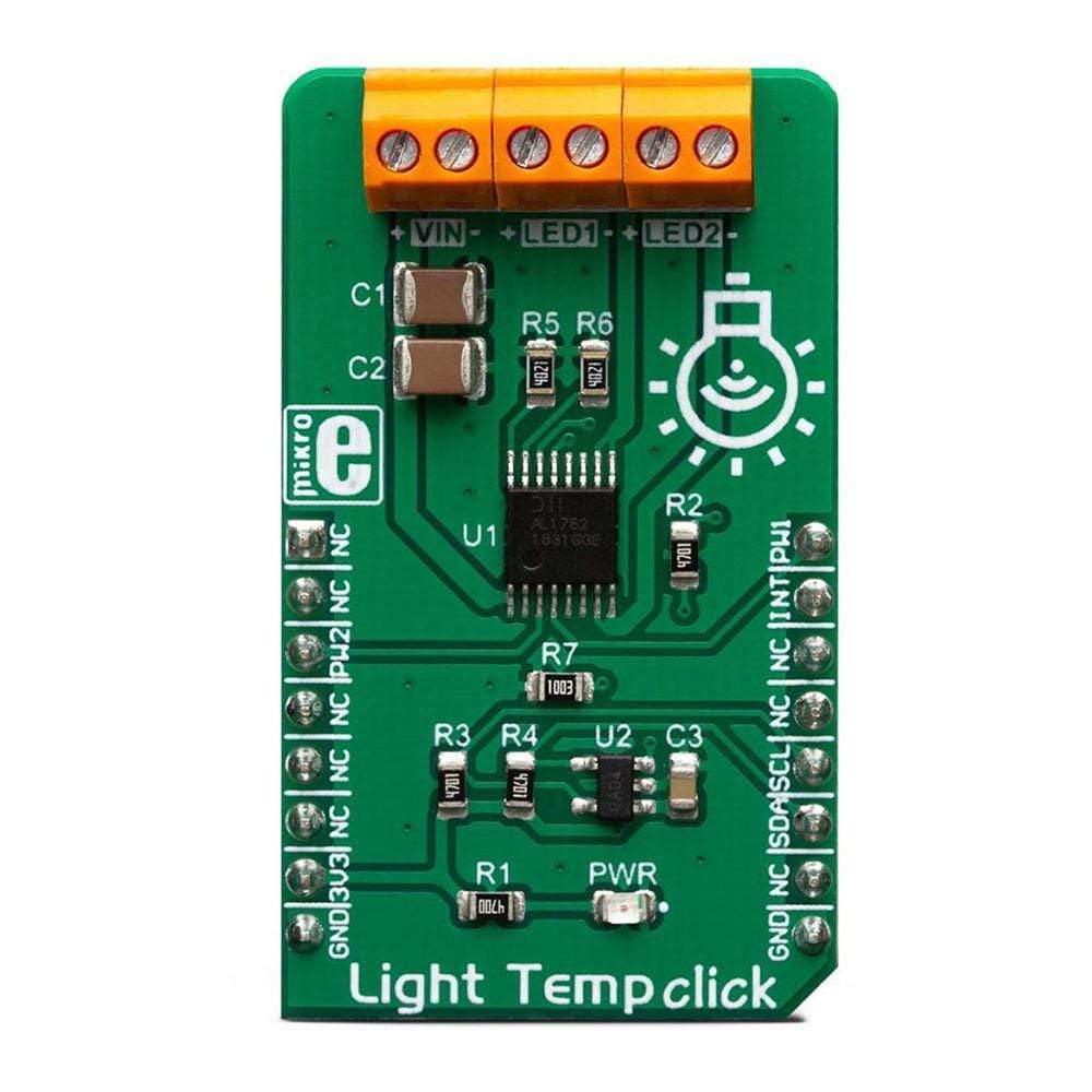
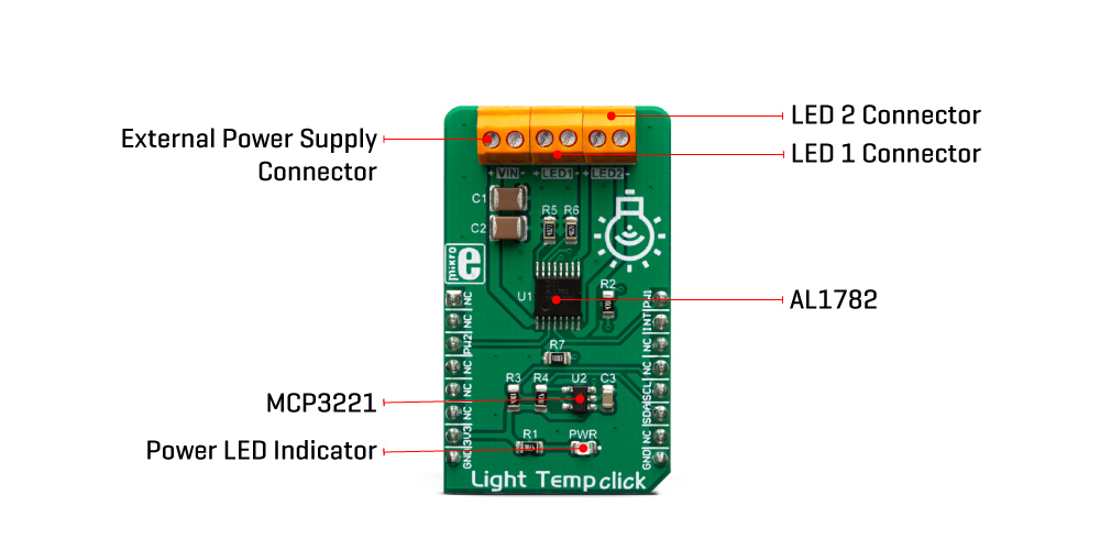
ONBOARD SETTINGS AND INDICATORS
| Label | Name | Default | Description |
|---|---|---|---|
| PWR | PWR | - | Power LED indicator |
| LED1 | LED1 | - | LED1 connector |
| LED2 | LED2 | - | LED2 connector |
| LED2 | LED2 | - | LED2 connector |
| VIN | VIN | - | External power supply connector |
| General Information | |
|---|---|
Part Number (SKU) |
MIKROE-3399
|
Manufacturer |
|
| Physical and Mechanical | |
Weight |
0.02 kg
|
| Other | |
EAN |
8606018714704
|
Frequently Asked Questions
Have a Question?
Be the first to ask a question about this.