Overview
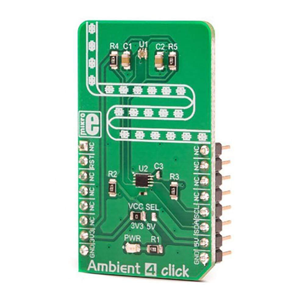
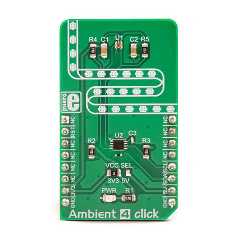
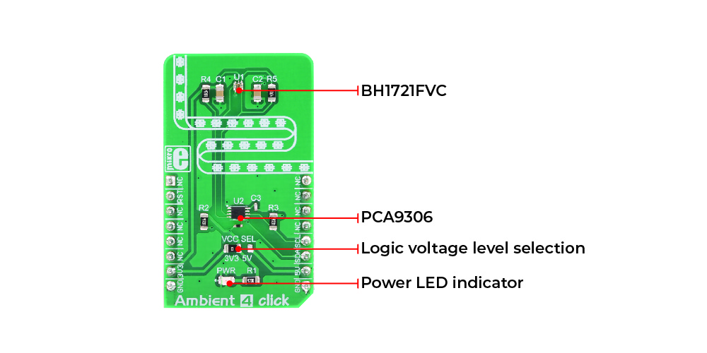
The Ambient 4 Click Board™ is a light intensity-sensing and measuring Click Board™, which features an accurate, light-intensity sensor labelled as BH1721FVC, made by ROHM Corporation. It offers a high measurement accuracy in the range between 1x to 1.35x of the actual light intensity. The spectral response of the sensor is calibrated to closely match the spectral response of the human eye. Thanks to its high level of integration, the sensor requires a minimal number of external components, allowing the Click Board™ to incorporate an additional level translating IC, ensuring a reliable data transfer over the industry-standard I2C interface.
Downloads
The influence of the light source type on the measurement accuracy is quite reduced. The sensor is capable of converting the light intensity from any type of light source, including daylight, fluorescent light, LED light, incandescent light, and so on. It also features a flickering filter, reducing the 50/60 Hz flickering influence. Its low power consumption, compact size, high sensitivity, and a high level of integration, make this sensor an ideal solution for both the IoT light-sensing applications, but also for portable or handheld devices which utilize an accurate light intensity sensing, such as the TFT/LCD screens, keypad backlight, cell phones, digital cameras, and similar.
How Does The Ambient 4 Click Board™ Work?
As mentioned previously, Ambient 4 Click Board™ uses the BH1721FVC, a 16-bit digital light sensor with the I2C serial interface, from ROHM Corporation. This sensor has many features that make it a perfect solution for small designs such as the The Ambient 4 Click Board™ is a light intensity-sensing and measuring Click Board™, which features an accurate, light-intensity sensor labelled as BH1721FVC, made by ROHM Corporation. . One of these features is certainly its high level of integration, that allows a minimal number of external components, leaving room for an additional I2C level translator IC, labelled as PCA9306, a reliable I2C level translator from Texas Instruments, proven in many designs. This allows a high number of microcontrollers (MCUs) to be interfaced with Ambient 4 click. The BH1721FVC sensor is also immune to flickering and its accuracy is not influenced by the light source type. It is calibrated so its spectral response is closely matched to a spectral response of the human eye.
The BH1721FVC sensor of the The Ambient 4 Click Board™ is a light intensity-sensing and measuring Click Board™, which features an accurate, light-intensity sensor labelled as BH1721FVC, made by ROHM Corporation. can operate in two modes: it can be operated in Low-Resolution mode and High-Resolution mode. While operating in the Low-Resolution mode, the measuring resolution is 8 lx per step. When operated in a High-Resolution mode, the accuracy is 1 lx per step. When sensing very low amounts of light, it is mandatory to use High-Resolution mode, since it is not possible to obtain valid results in Low-Resolution mode. The resolution can be also fine-tuned by changing the measurement time. This is used to increase the sensitivity of the sensor, as well as to reduce the influence of the optical window if one is mounted over the sensor. Increasing of the measurement time allows light amount down to 0.25 lx to be detected. The Low-Resolution mode, in general, allows much shorter measurement times, while high resolution will use longer to place the conversion data on the 16-bit output register.
As mentioned already, the spectral response of the sensor is closely matched to the response of the human eye. This means that the sensor outputs highest results for the light spectrum range between 500nm and 650 nm, which includes most of the light energy in the visible light spectrum: this is a color range from cyan to orange. The datasheet of the BH1721FVC offers a more accurate representation of the spectrum response, as well as for other operating parameters.
The sensitivity of the sensor is also affected by the incidence angle of the light rays. The BH1721FVC datasheet offers an accurate representation of the sensor's field of view (FOV), but a light source with the incidence angle of ±45˚ will result with the measured ratio of 0.8 times compared to the same light source intensity perpendicular to the surface of the sensor.
Since the sensor output result is 16-bit, it is stored in the LSB/MSB format, in two separate output registers. To obtain a measurement data in proper units (Lux, lx), a data conversion has to be performed by the firmware of the host MCU. The datasheet of the BH1721FVC contains these conversion formulas, although Ambient 4 click comes supported by a library that contains the functions that simplify the use of the Ambient 4 Click Board™ .
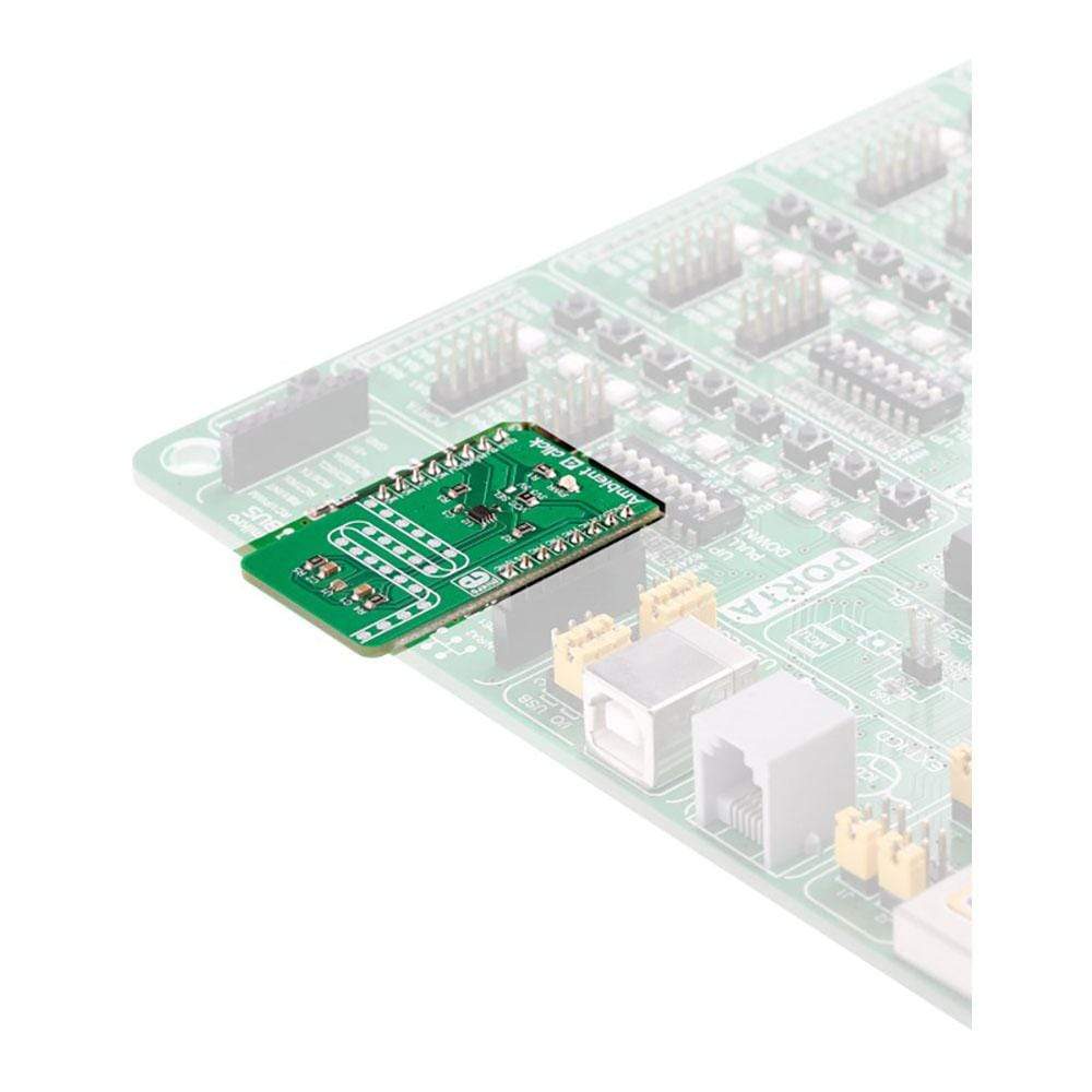
The 16-bit light intensity data is present at the I2C interface output. The I2C bus lines are routed to the aforementioned PCA9306 level translator. This allows interfacing with the wide range of different MCUs, both 3.3V, and 5V. It is worth mentioning that the sensor requires a reset after the power-up sequence, in order to set its internal registers to their defaults. This can be achieved by pulling the DVI line of the sensor to a LOW logic level for at least 1 µs.
An onboard SMD jumper labeled as VCC SEL offers a selection of the voltage at which the logic interface is operated (3.3V or 5V). I2C bus lines are routed to the respective mikroBUS™ pins, while the DVT line is routed to the RST pin of the mikroBUS™.
SPECIFICATIONS
| Type | Optical |
| Applications | This sensor is an ideal solution for both the IoT light sensing applications, and portable or handheld devices which utilize an accurate light intensity sensing, such as the TFT/LCD screens, keypad backlight, cell phones, digital cameras, and similar |
| On-board modules | BH1721FVC, a 16-bit digital light sensor with I2C serial interface, from ROHM; PCA9306, an I2C level translator from Texas Instruments |
| Key Features | A high resolution and range of light-intensity that can be measured, a spectral response similar to human eye, low power consumption, compact design ideal for building IoT applications, immune to flickering and fluorescent light sources, independent of the light source type, and more |
| Interface | I2C |
| Compatibility | mikroBUS |
| Click board size | M (42.9 x 25.4 mm) |
| Input Voltage | 3.3V or 5V |
PINOUT DIAGRAM
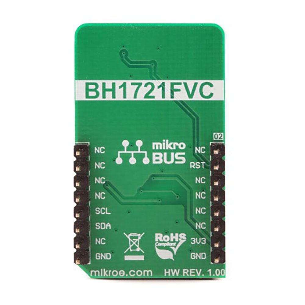
This table shows how the pinout on the Ambient 4 Click Board™ corresponds to the pinout on the mikroBUS™ socket (the latter shown in the two middle columns).
| Notes | Pin |  |
Pin | Notes | |||
|---|---|---|---|---|---|---|---|
| NC | 1 | AN | PWM | 16 | NC | ||
| Reset Chip | RST | 2 | RST | INT | 15 | NC | |
| NC | 3 | CS | RX | 14 | NC | ||
| NC | 4 | SCK | TX | 13 | NC | ||
| NC | 5 | MISO | SCL | 12 | SCL | I2C Clock | |
| NC | 6 | MOSI | SDA | 11 | SDA | I2C Data | |
| Power supply | 3.3V | 7 | 3.3V | 5V | 10 | 5V | Power supply |
| Ground | GND | 8 | GND | GND | 9 | GND | Ground |
ONBOARD JUMPERS AND SETTINGS
| Label | Name | Default | Description |
|---|---|---|---|
| LD1 | PWR | - | Power LED indicator |
| JP5 | VCC SEL | Left | Logic voltage level selection: left position 3.3V, right position 5V |
| General Information | |
|---|---|
Part Number (SKU) |
MIKROE-3199
|
Manufacturer |
|
| Physical and Mechanical | |
Weight |
0.018 kg
|
| Other | |
Country of Origin |
|
HS Code Customs Tariff code
|
|
EAN |
8606018713554
|
Warranty |
|
Frequently Asked Questions
Have a Question?
Be the first to ask a question about this.


