


Mikroelektronika d.o.o.
7x10 B Click Board™
7x10 B Click Board™
SKU: MIKROE-2789
Couldn't load pickup availability
Overview
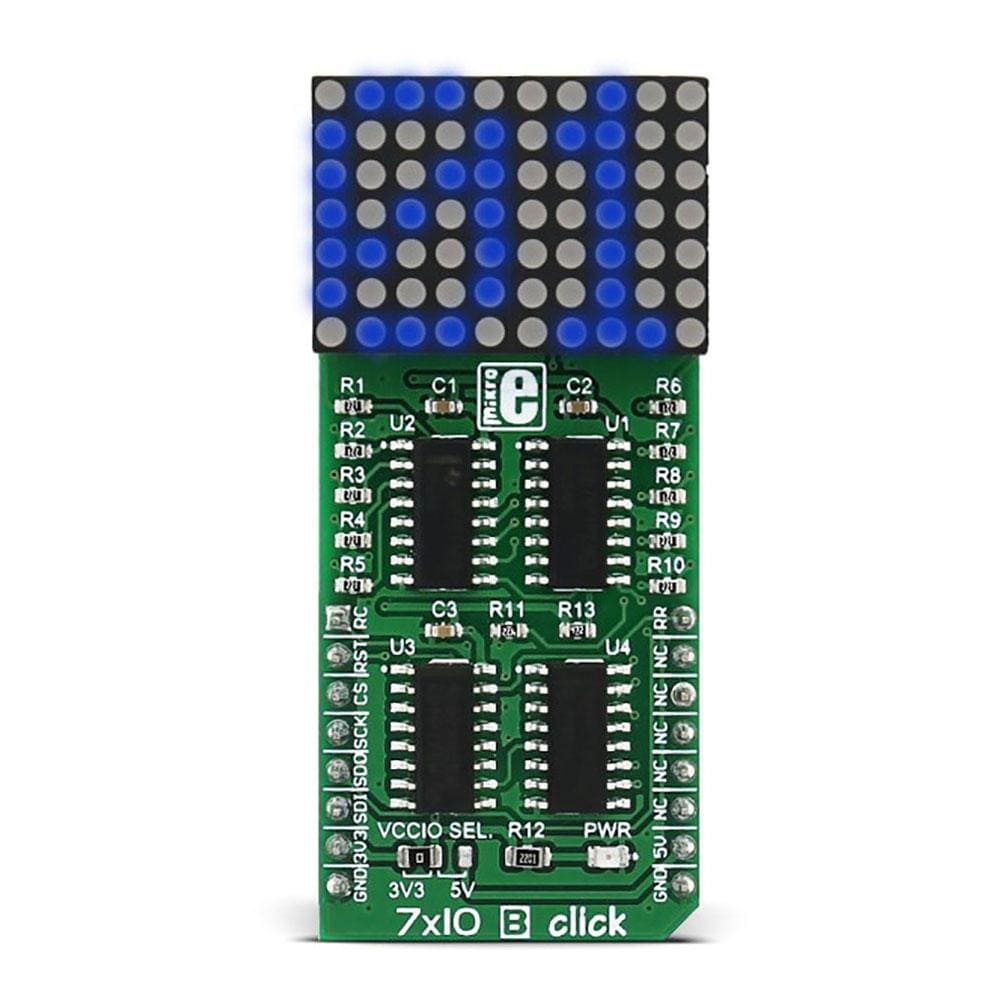
The 7x10 B Click Board™ is a LED dot matrix display Click Board™, which can be used to display graphics or letters in a very simple and easy way. The Click Board™ has two LED dot matrix modules with 7x5 stylish, round, dot-like LED elements.
These displays produce clean and uniform patterns since the elements are optically isolated from each other and there is no light bleeding between the adjacent LED cells. Additionally, turn-on and turn-off times of the matrix cells are optimised for a clean and fluid display performance, with no flickering or lag.
Downloads
The 7x10 B Click Board™ is a LED dot matrix display click, which can be used to display graphics or letters in a very simple and easy way. The click board has two LED dot matrix modules with 7x5 stylish, round, dot-like LED elements. These displays produce clean and uniform patterns since the elements are optically isolated from each other and there is no light bleeding between the adjacent LED cells. Additionally, turn-on and turn-off times of the matrix cells are optimized for a clean and fluid display performance, with no flickering or lag.
The 7x10 B Click Board™ can be used in a lot of different applications that require a clearly visible display of text or graphics, such as the public clock displays, temperature displays and similar. By using functions provided by MikroElektronika, it is possible to make a text scroller in a very simple way, greatly expanding the functionality of the 7x10 click.
How Does The 7x10 B Click Board™ Work?
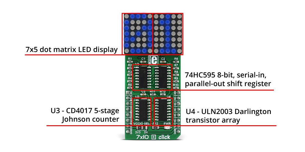
Two 7x5 LED dot matrix modules form a display. A single LED matrix module is composed of 35 LED elements, grouped in rows and columns. The LED elements in one row have their cathodes connected and routed to a single row pin. The LED elements in one column have their anodes connected and routed to a single column pin. Multiplexed like this, modules have a fairly low number of pins (12 per module), making them suitable to be driven by shift registers and a decade counter ICs. The driver circuit consists of two 74HC595 - 8bit, serial input - parallel output shift registers, one CD4017 - a Jonson topology decade counter with 10 outputs, and one ULN2003A - an IC with seven integrated Darlington transistor pairs, all chips produced by Texas Instruments.
The device communicates with the host MCU via the SPI interface. Two 8bit words of information are pushed through the serial data input pin of the first 74HC595 shift register IC. Since there are 5 columns on one module, both of these bytes must have their three MSB set to 0. Two shift register ICs (SR) are connected so that the serial data output of the first SR is connected to the serial data input of the second SR. When more than 8 bits are clocked in the first SR, they will start pushing (shifting) the bits serially into the second SR. After both of the internal storage registers of the SRs are loaded with the data this way, the SPI communication should be terminated (SCK signal stopped) and the rising edge of the LATCH pin (routed to mikroBUS™ CS pin) will cause the stored data to appear on the output pins of two SRs, in parallel form. This will not light up the corresponding LED elements yet; it will only polarize their anodes. To complete LEDs current path, their cathodes must be connected to ground. This is where the CD4017 and ULN2003 ICs are used.
The ULN2003 IC is used to drive rows of the dot matrix displays, by sinking the current on the active row. When there is no signal at the low-current side inputs of the ULN2003 IC, its outputs will be in a high impedance mode (High-Z), causing the inactive rows to be disconnected and their current path - obstructed. None of the LED elements on a disconnected row will be able to light up, even if their anodes were polarized by the SRs. To activate one of the 7 input channels of the ULN2003 IC, the CD4017 decade counter IC is used. It is perfect for this task since it will shift forward its active output for one position, with every clock pulse. Again, since this is a decade counter (10 outputs), only first 7 channels are used. To skip last 3 cycles, the counter IC needs to be reset, by means of the RST pin, routed to the RST pin of the mikroBUS™. When the specific row is activated, LEDs on that row, which have their anodes polarized by the SRs, will be lit - since the current will be able to sink through the Darlington pairs to the ground. This is how the multiplication is implemented.
The design of the decade counter allows only one row to be active at a time. So, in order to see the complete picture on a led matrix, the row scanning has to be fast enough, so that the effect called persistent vision takes place. It produces an illusion of a complete image, even if only one row is seen at a time - because the human eye is not able to detect very fast changes of light. Scanline method is a very old method for displaying a picture on a number of various displays - starting with old CRT displays, up to modern TFT computer screens.
However, for this effect to work, the timing is very important. To switch to the next row, the data on the previous row needs to be displayed first. Therefore, the clock impulse for the CD4017 needs to occur after all the 16 bits from the SPI bus were clocked in the SRs and latched out to LED elements, plus a small delay to allow the line to be absorbed by the human eye. Therefore, the R_CLK clock pin of the CD4017 is routed to the AN pin of the mikroBUS™.
The #MR pin is used to clear the data in the internal storage register of the ICs. The LOW logic level on this pin will clear the content of this register but will not turn off the outputs already activated. The #MR pin is routed to the RST pin of the mikroBUS™ and it is pulled to a HIGH logic level by the onboard resistor.
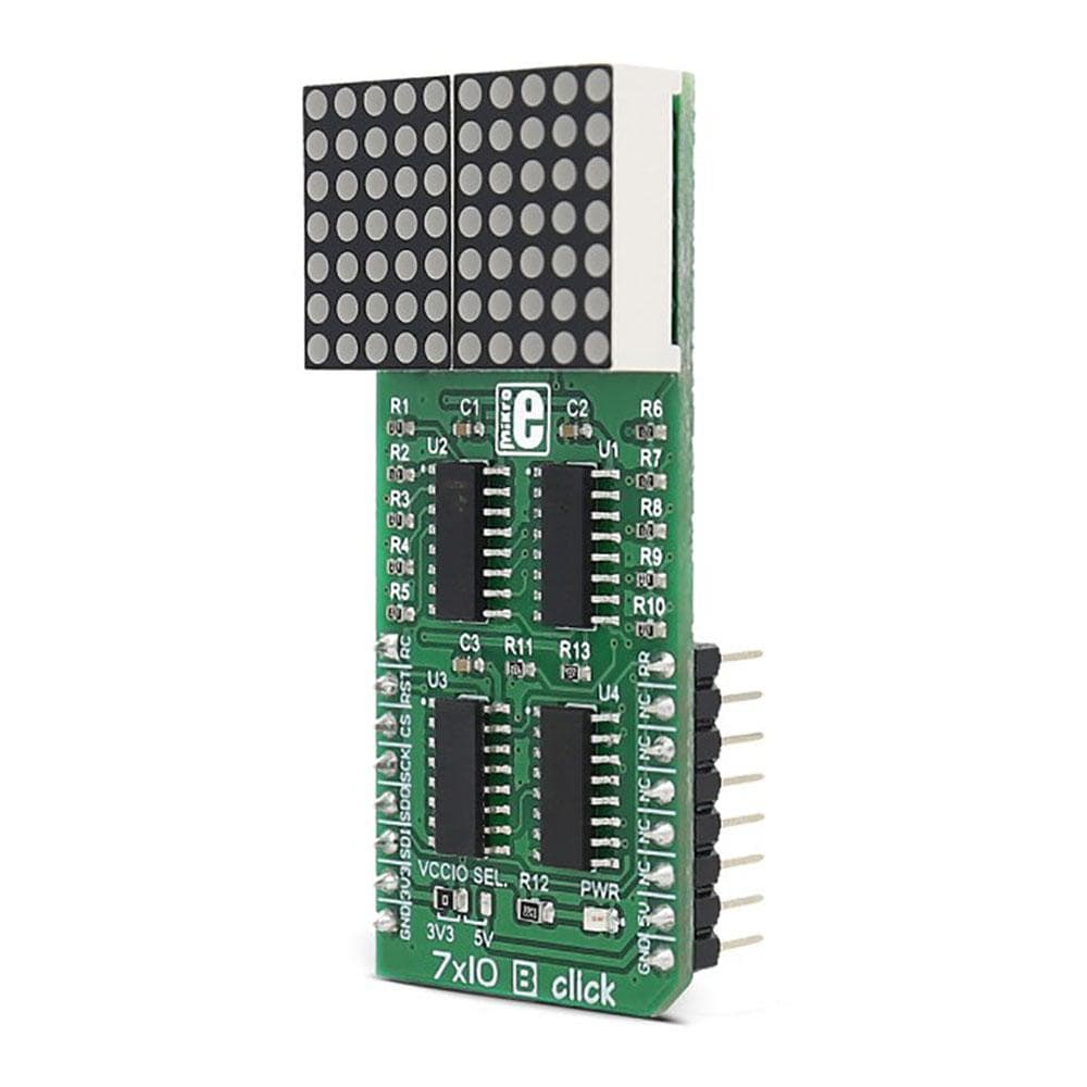
The 7x10 B Click Board™ is able to work with both 3.3V and 5V MCUs. The operating voltage selection can be done by the onboard SMD jumper, labelled as VCCIO SEL.
The provided library contains functions which can be used to easily initialize and work with the 7x10 click. The demo application shows how to use the included functions and can be used as a reference for custom design. More information about the functions and how to operate 7x10 click can be found on the Let's learn article, HERE.
SPECIFICATIONS
| Type | LED Matrix |
| Applications | The 7x10 B Click Board™ can be used for graphical display of information, such as public clock displays, temperature displays, text scrollers and similar applications that display clearly visible low-resolution graphics or text |
| On-board modules | 7x5 dot matrix LED display, 74HC595, an 8bit shift register, CD4017, a 5-stage Johnson counter, ULN2003, a Darlington transistors array |
| Key Features | High degree of readability, fluid and clean display of text and graphics, provided software libraries offer functions for easy text scrollers |
| Interface | GPIO,SPI |
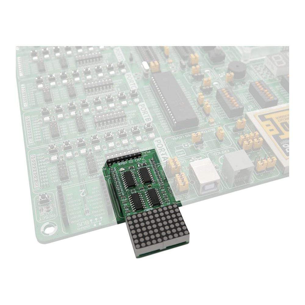
| Compatibility | mikroBUS |
| Click board size | L (57.15 x 25.4 mm) |
| Input Voltage | 3.3V or 5V |
PINOUT DIAGRAM
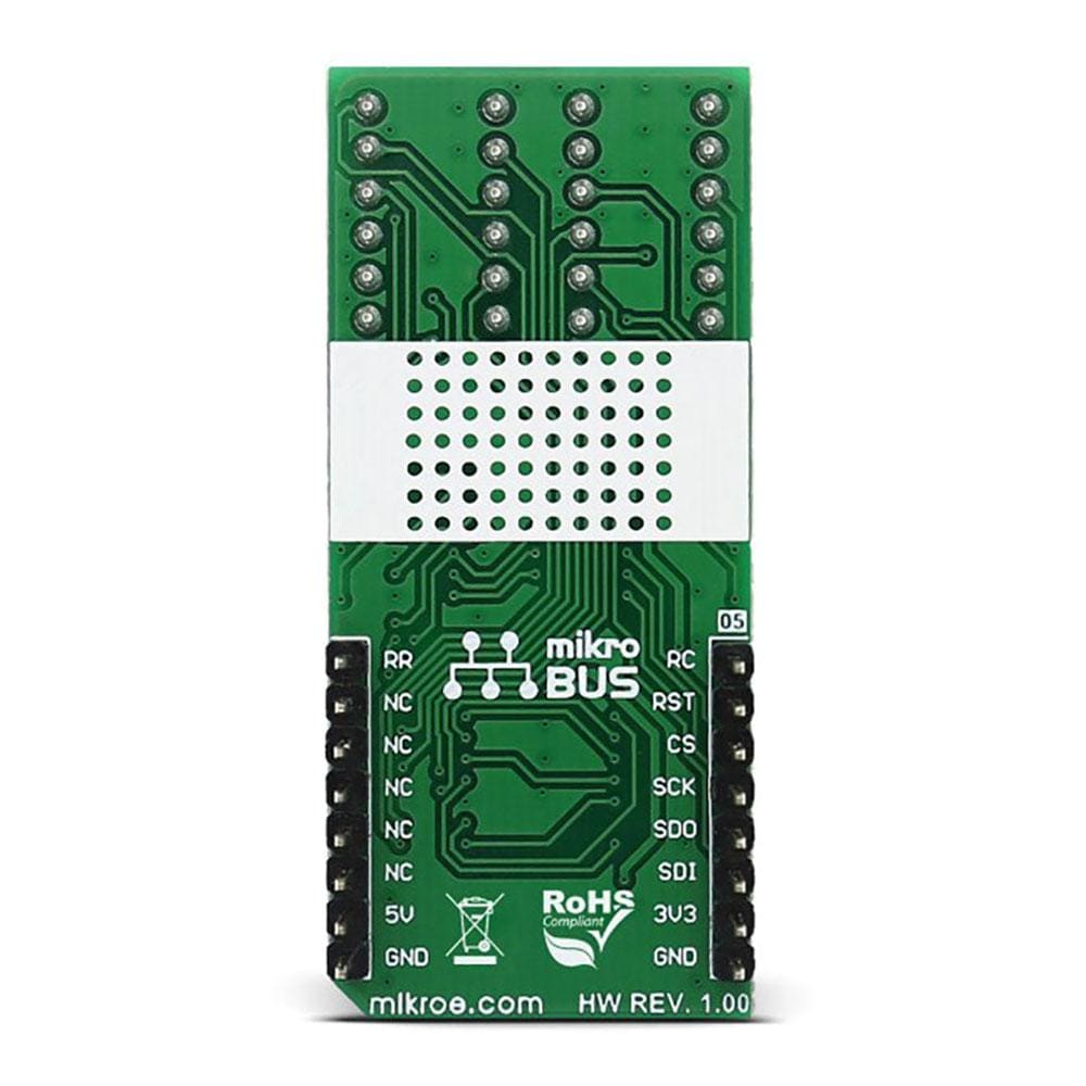
This table shows how the pinout of the 7x10 B Click Board™ corresponds to the pinout on the mikroBUS™ socket (the latter shown in the two middle columns).
| Notes | Pin | Pin | Notes | ||||
|---|---|---|---|---|---|---|---|
| CD4017 Clock | RC | 1 | AN | PWM | 16 | RR | CD4017 Reset |
| 74HC595 Reset | RST | 2 | RST | INT | 15 | NC | |
| 74HC595 Latch | CS | 3 | CS | TX | 14 | NC | |
| SPI Clock | SCK | 4 | SCK | RX | 13 | NC | |
| SPI Data out | SDO | 5 | MISO | SCL | 12 | NC | |
| SPI Data in | SDI | 6 | MOSI | SDA | 11 | NC | |
| Power Supply | +3.3V | 7 | 3.3V | 5V | 10 | +5V | Power Supply |
| Ground | GND | 8 | GND | GND | 9 | GND | Ground |
ONBOARD SETTINGS AND INDICATORS
| Designator | Name | Default Position | Description |
|---|---|---|---|
| LD1 | PWR | - | Power LED indicator |
| JP1 | VCCIO SEL | Left | Power supply selection: left position 3V3, right position 5V |
| General Information | |
|---|---|
Part Number (SKU) |
MIKROE-2789
|
Manufacturer |
|
| Physical and Mechanical | |
Weight |
0.022 kg
|
| Other | |
EAN |
8606018711666
|
Frequently Asked Questions
Have a Question?
Be the first to ask a question about this.