

Overview
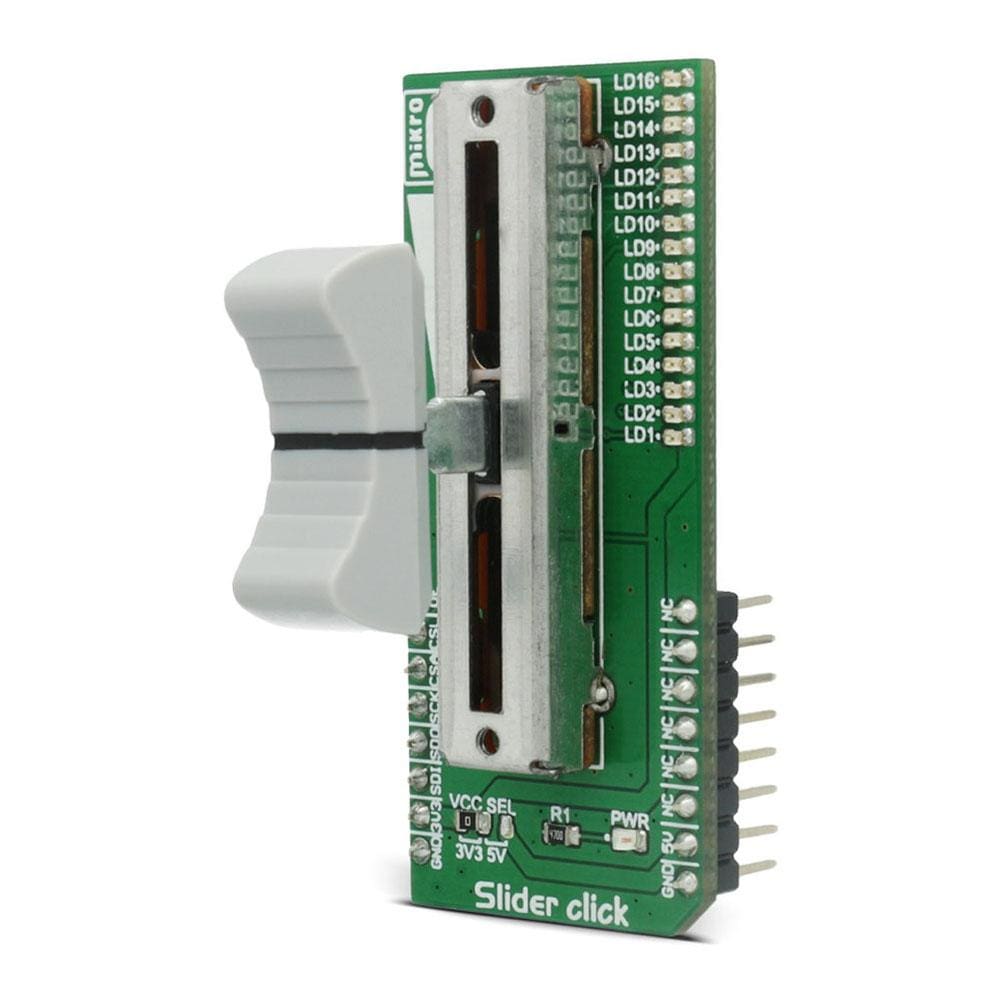
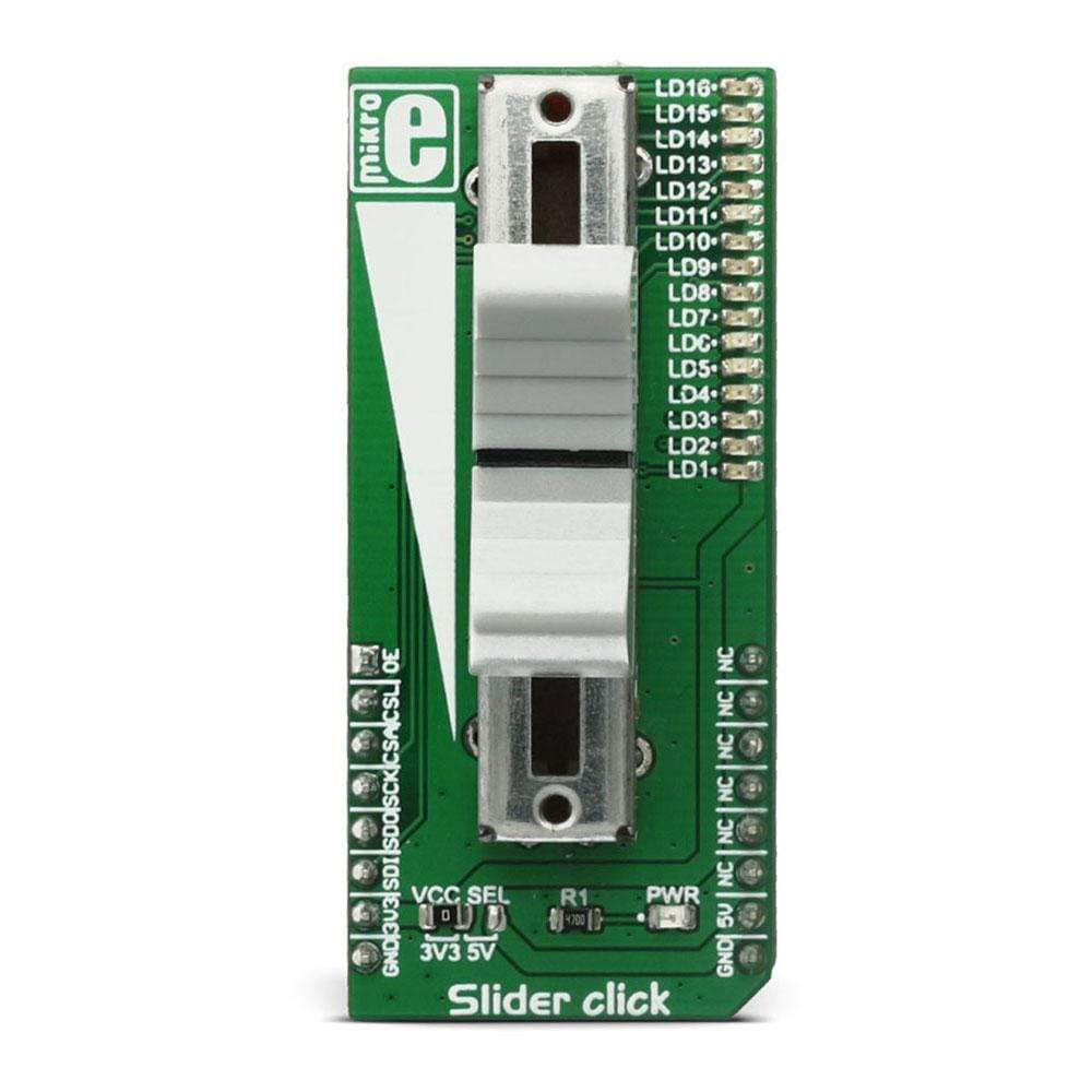
The Slider Click Board™ features a mechanical slide action potentiometer - a slider, which gives a nice feeling when actuating, along with 16 SMD LEDs, that can be used for any kind of visual feedback. The on-board high-resolution 22-bit ADC can detect even the smallest move, faithfully capturing the smoothness of the slider movement, while digitizing its position. The 16 on-board SMD LEDs can give a nice visual feedback of the slider position, but those LEDs can also be used for other purposes since they are not hardwired to the slider.
The Slider Click Board™ can be used to control various digital applications with an accurate and comfortable slider potentiometer, while the LEDs can be used to display the desired information in a form of a bar or a position. For example, Slider Click Board™ can be used to control a quad digital potentiometer, such as the one that can be found on DIGIPOT 5 Click Board™, while displaying the position of the selected digital wiper on the LEDs.
Downloads
How Does The Slider Click Board™ Work?
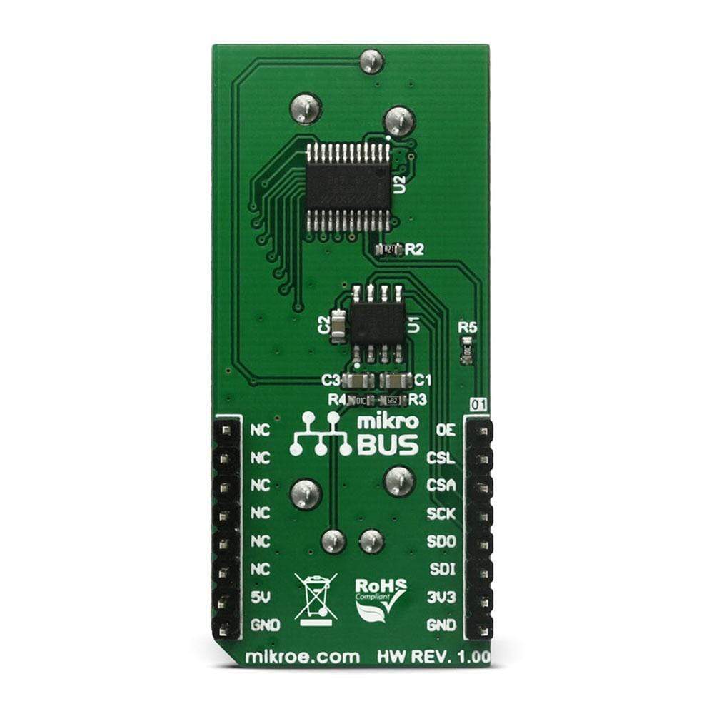
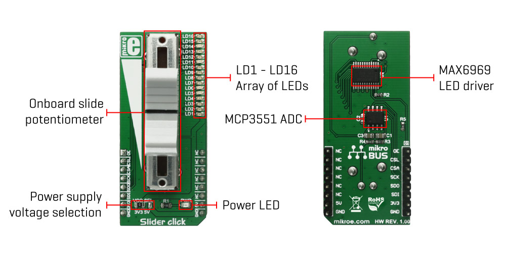
The Slider Click Board™ consists of two sections: the first section is the slider section itself, with the sliding potentiometer end terminals connected between GND and the VCC, and the wiper connected to the MCP3551 IC, which is a low-power, single-channel 22-bit delta-sigma ADC from Microchip. The slider acts as a voltage divider so that the voltage between the GND and the wiper position is determined by the slider position. This voltage is then applied to the input pin of the 22bit ADC converter and converted to a digital value. The MCP3551 has its SPI lines routed to the mikroBUS™ so that the values can be read easily by the MCU.
The second section of the Slider Click Board™ consists of the MAX6969, a well know 16-port, constant-current LED driver from Maxim Integrated, used to control the SMD LEDs. The MAX6969 IC uses the same SPI lines as the ADC, but to avoid data collision, different chip select (CS) line is used. While the ADC uses the CS line routed to the CS pin of the mikroBUS™, the LED driver uses the RST line of the mikroBUS™ as the chip select input. This allows to work with both ICs independently. MAX6969 output enable (OE) pin is routed to the AN pin of the mikroBUS™, making it easy to completely turn off the output stage of the MAX6969, by setting this pin to a HIGH logic state. If left floating, this pin will be pulled down to the GND by the 10K resistor. The output LED current is constant and it is set to around 20mA by the resistor on the SET pin of the MAX6969.
The Slider Click Board™ can work with both 3.3V and 5V, depending on the used MCU capabilities. This can be done by switching the VCC SEL SMD jumper to the desired position.
SPECIFICATIONS
| Type | Potentiometer |
| Applications | The Slider Click Board™ can be used to control various digital applications with an accurate and comfortable slider potentiometer, such as the PWM ratio for the lighting, digital volume for the audio amplifiers, BLDC motor speed control and similar. |
| On-board modules | MCP3551 - a single channel 22bit delta-sigma ADC from Microchip, MAX6969 - a 16 segment LED driver from Maxim Integrated |
| Key Features | It features a smooth action slider pot, that can be used to control any digital application. The onboard 22bit ADC allows a very precise and faithful capture of the slider movement. 16 LEDs can be used independently for a visual feedback. |
| Interface | GPIO,SPI |
| Compatibility | mikroBUS |
| Click board size | L (57.15 x 25.4 mm) |
| Input Voltage | 3.3V or 5V |
PINOUT DIAGRAM
This table shows how the pinout of the Slider Click Board™ corresponds to the pinout on the mikroBUS™ socket (the latter shown in the two middle columns).
| Notes | Pin |  |
Pin | Notes | |||
|---|---|---|---|---|---|---|---|
| LED Driver Output Enable | OE | 1 | AN | PWM | 16 | NC | |
| LED Driver SPI CS | CSL | 2 | RST | INT | 15 | NC | |
| AD Converter SPI CS | CSA | 3 | CS | RX | 14 | NC | |
| SPI Clock | SCK | 4 | SCK | TX | 13 | NC | |
| SPI Data Out | SDO | 5 | MISO | SCL | 12 | NC | |
| SPI Data In | SDI | 6 | MOSI | SDA | 11 | NC | |
| Power Supply | +3.3V | 7 | 3.3V | 5V | 10 | +5V | Power Supply |
| Ground | GND | 8 | GND | GND | 9 | GND | Ground |
ONBOARD SETTINGS AND INDICATORS
| Label | Name | Default | Description |
|---|---|---|---|
| LD0 | PWR | - | Power LED indicator |
| JP1 | VCC SEL | Left | Power supply voltage selection: left position 3V3, right position 5V |
| P1 | P1 | - | On-board slide potentiometer |
| LD1-LD16 | LD1-LD16 | - | Array of 16SMD LEDs |
ith mikroSDK - MikroElektronika Software Development Kit. To ensure proper operation of mikroSDK compliant click board demo applications, mikroSDK should be downloaded from the LibStock and installed for the compiler you are using.
| General Information | |
|---|---|
Part Number (SKU) |
MIKROE-2702
|
Manufacturer |
|
| Physical and Mechanical | |
Weight |
0.025 kg
|
| Other | |
Country of Origin |
|
HS Code Customs Tariff code
|
|
EAN |
8606018711741
|
Warranty |
|
Frequently Asked Questions
Have a Question?
Be the first to ask a question about this.


