


Mikroelektronika d.o.o.
DC Motor 5 Click Board™
DC Motor 5 Click Board™
SKU: MIKROE-2699
Couldn't load pickup availability


Overview
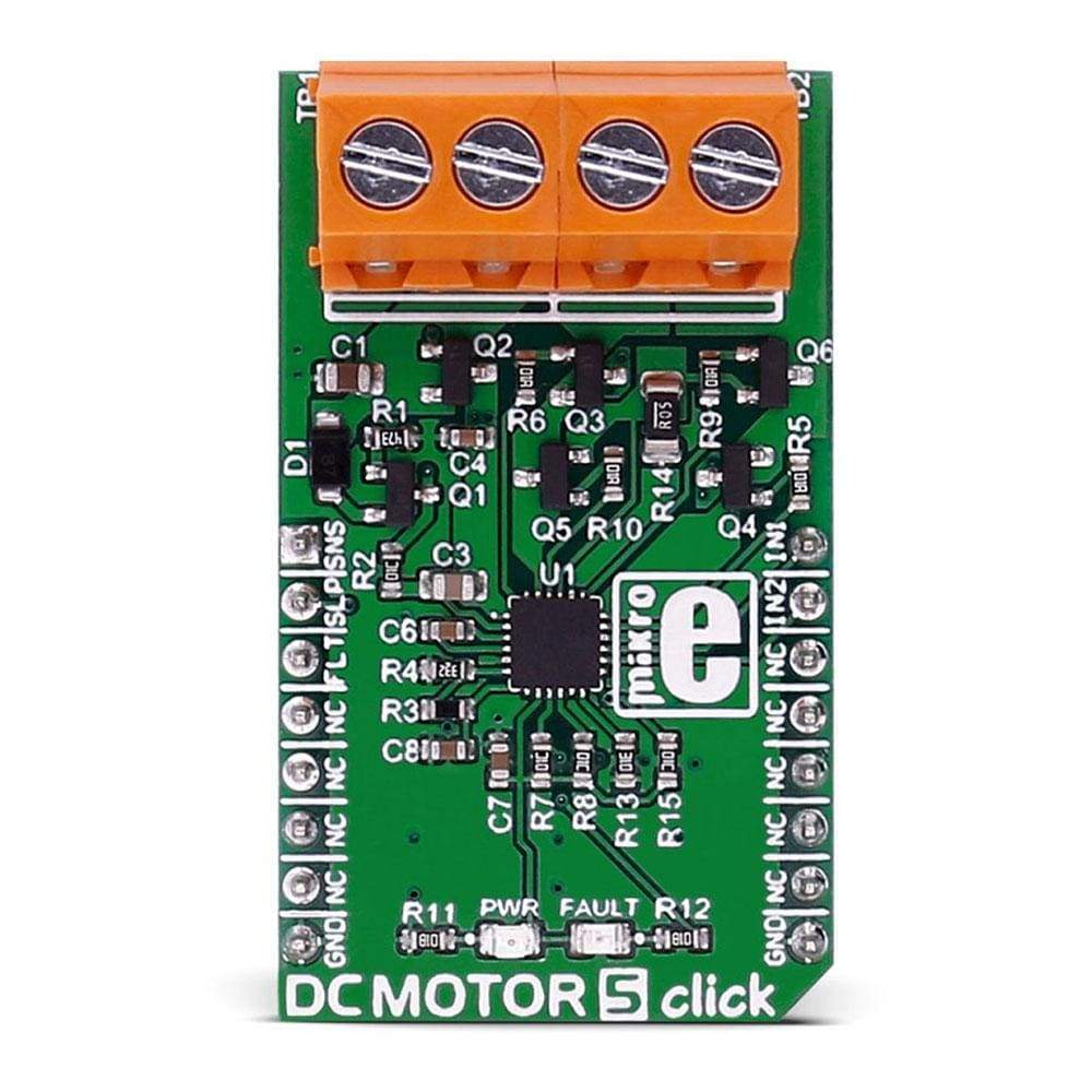
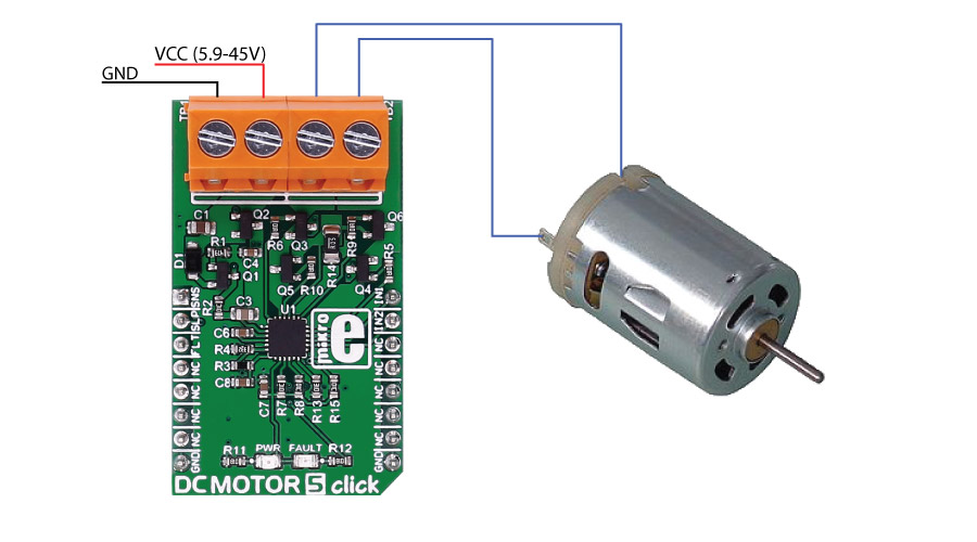
The DC Motor 5 Click Board™ carries the DRV8701 brushed DC motor gate driver from Texas Instruments.
The DC Motor 5 Click Board™ is designed to run on an external power supply. It communicates with the target MCU over the following pins on the MikroBUS line: AN, RST, CS, PWM, and INT.
Downloads
The DC Motor 5 Click Board™ carries the DRV8701 brushed DC motor gate driver from Texas Instruments. The click is designed to run on an external power supply. It communicates with the target MCU over the following pins on the mikroBUS™ line: AN, RST, CS, PWM, and INT.
DRV8701 DRIVER FEATURES
The DRV8701 is an H-bridge gate driver (also called a pre-driver or controller). The device integrates FET gate drivers in order to control four external NMOS FETs. The device can be powered with a supply voltage between 5.9V and 45V.
Internal protection functions are provided: under-voltage lockout, charge pump faults, overcurrent shutdown, short-circuit protection, pre-driver faults, and overtemperature.
How Does The DC Motor 5 Click Board™ Work?
The motor's velocity and direction can be adjusted with two PWM input signal's.
SPECIFICATIONS
| Type | Brushed |
| Applications | Industrial brushed-DC motors, robotics, home automation, etc. |
| On-board modules | DRV8701 Brushed DC Motor Full-Bridge Gate Driver |
| Key Features | supply voltage between 5.9V and 45V |
| Interface | GPIO |
| Compatibility | mikroBUS |
| Click board size | M (42.9 x 25.4 mm) |
| Input Voltage | External |
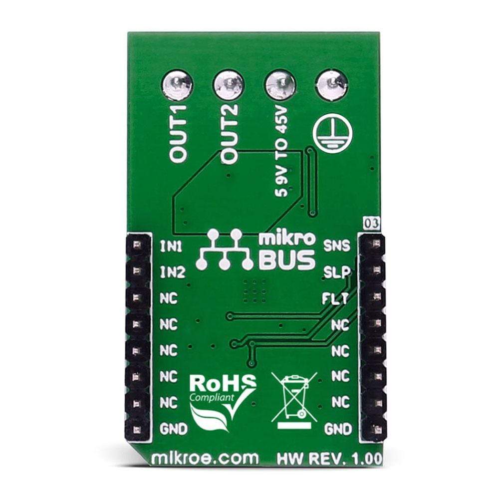
PINOUT DIAGRAM
This table shows how the pinout of the DC Motor 5 Click Board™ corresponds to the pinout on the mikroBUS™ socket (the latter shown in the two middle columns).
| Notes | Pin | Pin | Notes | ||||
|---|---|---|---|---|---|---|---|
| Sense comparator output | SNSO | 1 | AN | PWM | 16 | IN1 | Input signal 1 |
| Device sleep mode | SLEEP | 2 | RST | INT | 15 | IN2 | Input signal 2 |
| Fault indication pin | FAULT | 3 | CS | TX | 14 | NC | |
| NC | 4 | SCK | RX | 13 | NC | ||
| NC | 5 | MISO | SCL | 12 | NC | ||
| NC | 6 | MOSI | SDA | 11 | NC | ||
| NC | 7 | 3.3V | 5V | 10 | NC | ||
| Ground | GND | 8 | GND | GND | 9 | GND | Ground |
BUTTONS AND LEDS
| Designator | Name | Type | Description |
|---|---|---|---|
| LD1 | PWR | LED | Power Indication LED |
| TB1 | VM | CD | Voltage input connector |
| TB2 | Out_M | CD | Motor connector |
MAXIMUM RATINGS
| Description | Min | Typ | Max | Unit |
|---|---|---|---|---|
| Supply VOltage | 5.9 | 45 | V | |
| Source Current | 6 | 150 | mA | |
| Sink Current | 12.5 | 300 | mA | |
| Applied PWM signal | 100 | kHz | ||
| Operating ambient temperature | -40 | 125 | ℃ |
| General Information | |
|---|---|
Part Number (SKU) |
MIKROE-2699
|
Manufacturer |
|
| Physical and Mechanical | |
Weight |
0.025 kg
|
| Other | |
EAN |
8606018710928
|
Frequently Asked Questions
Have a Question?
Be the first to ask a question about this.