


Mikroelektronika d.o.o.
ATA663211 Click Board™
ATA663211 Click Board™
SKU: MIKROE-2335
Couldn't load pickup availability

Key Features
Overview
The ATA663211 Click Board™ carries an Atmel LIN transceiver IC designed to handle low-speed data communication in vehicles and in industrial applications with electrically harsh environments. The LIN connection is established by attaching wires to the on-board screw terminals.
Downloads
The ATA663211 Click Board™ communicates with the target MCU through the UART interface and runs on a 3.3V power supply.
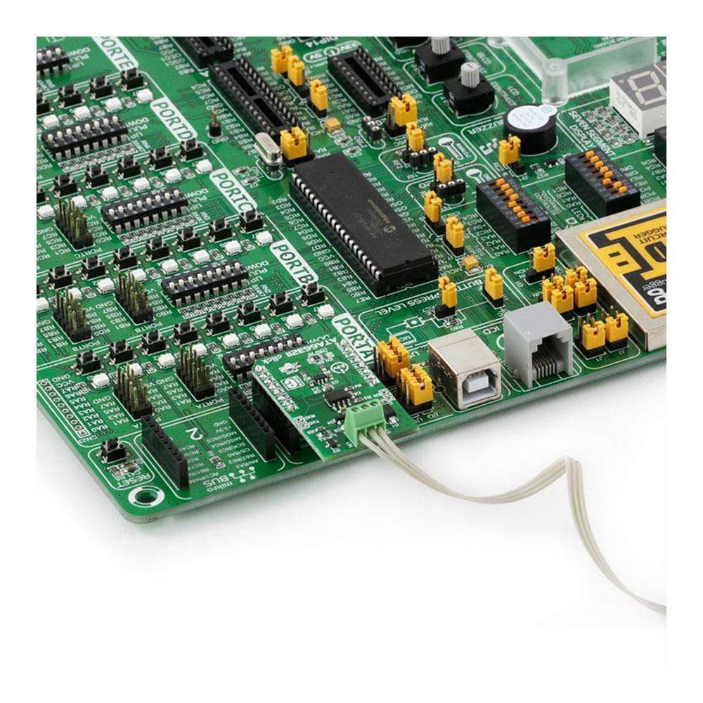
The ATA663211 Click Board™ can aslo be used as a standalone LIN transceiver, without being connected to a mikroBUS™ socket. An onboard LDO (low-dropout regulator) enables it to get its power supply through the VS line screw terminal.
LIN TRANSCEIVER
LIN or Local Interconnect Network is a protocol used for communicating between components in vehicles. These days cars have hundreds of sensor applications to measure things like temperature, pressure, air flow, speed, etc. All these applications need to communicate with the main system.
The LIN bus was created by European car manufacturers to establish a new, uniform communication standard. It can be used with CAN (Controller Area Network), but LIN is more cost-effective for simple sensor networks in vehicles.
For more information see our Learn article on the LIN network protocol.
LOW CURRENT CONSUMPTION
The IC has three very low power modes: normal, sleep and fail-safe. In sleep mode the current consumption is typically 9μA – this is the lowest current consumption mode. It automatically switches to fail-safe mode at system power-up or after a wake-up event. In fail-safe mode it typically uses 80μA.
APPLICATIONS
Automotive industry and other electrically harsh environments.
SPECIFICATIONS
| Type | LIN |
| Applications | Automotive industry and other electrically harsh environments |
| On-board modules | Atmel LIN transceiver IC |
| Key Features | Data communication up to 20Kbaud, Power consumption 9μA in sleep mode, Bus pin is over-temperature and short-circuit protected |
| Interface | GPIO,UART |
| Compatibility | mikroBUS |
| Click board size | M (42.9 x 25.4 mm) |
| Input Voltage | 3.3V |
WHAT DOES A LIN TRANSCEIVER DO
LIN or Local Interconnect Network is a protocol used for communication between components in vehicles. The car industry has changed profoundly during this century. Cars have hundreds of sensor applications to measure things like temperature, pressure, air flow, speed, etc. All these applications need to communicate with the main system. The LIN bus was created by European car manufactures in order to establish a new, uniform communication standard. It can be used with CAN (Controller Area Network), but LIN is more cost-effective for simple sensor networks in vehicles.
But what is the difference between LIN and CAN network protocols? CAN is an a really complex interface, and with so many electronic components in a car the manufactures needed a cheaper alternative. The LIN interface is simpler than CAN — LIN uses a single wire communication and the slave nodes are clocked by only one master. CAN interface has nodes that can act independently, receive messages and act. It can have more than one master on the CAN bus. A LIN network is usually made of up to 16 nodes - one master and 15 slaves. This serial communications protocol is also well suited for other industrial applications with electrically harsh environments.
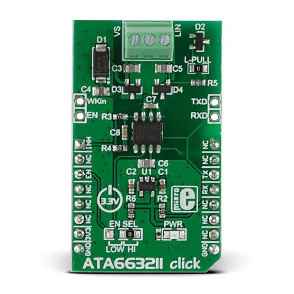
SCREW TERMINALS
The click has three screw terminals: VS line for the power supply (up to 40V), GND for ground and LIN line for connecting to the other transceiver LIN line.
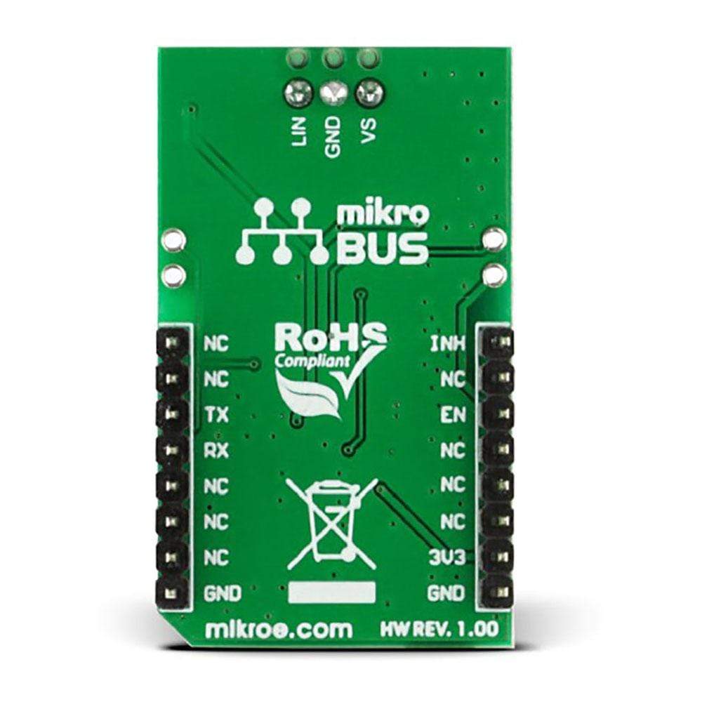
Pinout Diagram
This table shows how the pinout of the ATA663211 Click Board™ corresponds to the pinout on the mikroBUS™ socket.
| Notes | Pin | Pin | Notes | ||||
|---|---|---|---|---|---|---|---|
| controls an external voltage regulator | INH | 1 | AN | PWM | 16 | NC | |
| NC | 2 | RST | INT | 15 | NC | ||
| controls the operating mode of the device | EN | 3 | CS | TX | 14 | RX | UART Transmit |
| NC | 4 | SCK | RX | 13 | TX | UART Receive | |
| NC | 5 | MISO | SCL | 12 | NC | ||
| NC | 6 | MOSI | SDA | 11 | NC | ||
| +3.3V power input | +3.3V | 7 | 3.3V | 5V | 10 | NC | |
| Ground | GND | 8 | GND | GND | 9 | GND | Ground |
MAXIMUM RATINGS
This table shows how the pinout on ATA663211 Click Board™ corresponds to the pinout on the mikroBUS™ socket (the latter shown in the two middle columns).
| Description | Min | Typ | Max | Unit |
|---|---|---|---|---|
| Supply voltage VS | -0.3 | / | +40 | V |
| Logic pins voltage levels (RxD, TxD, EN,NRES) | -0.3 | / | +5.5 | V |
| Logic output DC currents | -5 | / | +5 | mA |
| LIN - DC voltage - Pulse time < 500ms |
-27 | / | +40 +43.5 |
V V |
| INH -DC voltage |
-0.3 | / | Vs+0.3 | V |
| WKin voltage levels - DC voltage -Transient voltage according to ISO7637 (coupling 1nF), (with 2.7K serial resistor) |
-0.3 -150 |
/ | +40 +100 |
V |
| ESD according to IBEE LIN EMC Test specification 1.0 following IEC 61000-4-2 - Pin VS, LIN to GND, WKin (with ext. circuitry acc. applications diagram) |
+-6 | kV | ||
| ESD HBM following STM5.1 with 1.5kW/100pF - Pin VS, LIN, INH to GND - Pin WKin to GND |
±6 ±5 |
kV | ||
| HBM ESD ANSI/ESD-STM5.1 JESD22-A114 AEC-Q100 (002) |
±3 | kV | ||
| CDM ESD STM 5.3.1 | ±750 | V | ||
| Machine Model ESD AEC-Q100-RevF(003) |
±200 | V | ||
| Junction temperature | +150 | C | ||
| Storage temperature | -55 | +150 | C |
ADDITIONAL PINS AND JUMPERS
In addition to mikroBUS the click has four additional pins:
- WKIN — high-input voltage pin used to wake up the device from sleep mode.
- EN — controls the operating mode of the device.
- TXD and RXD — additional UART transmit and receive lines.
EN SEL jumper enables pin selection mode (by default it is always on, good for standalone purposes) otherwise can be LOW - then it is connected to EN pin on the mikroBUS.
| General Information | |
|---|---|
Part Number (SKU) |
MIKROE-2335
|
Manufacturer |
|
| Physical and Mechanical | |
Weight |
0.03 kg
|
| Other | |
EAN |
8606015079349
|
Frequently Asked Questions
Have a Question?
Be the first to ask a question about this.