


Mikroelektronika d.o.o.
SKU: MIKROE-2063RTC 6 Click Board
RTC 6 Click Board
Couldn't load pickup availability
The RTC6 Click Board™ carries Microchip's MCP79410 Real-Time Clock/Calendar IC with built-in 64 bytes of battery-backed SRAM an additional 1 Kbit of EEPROM.
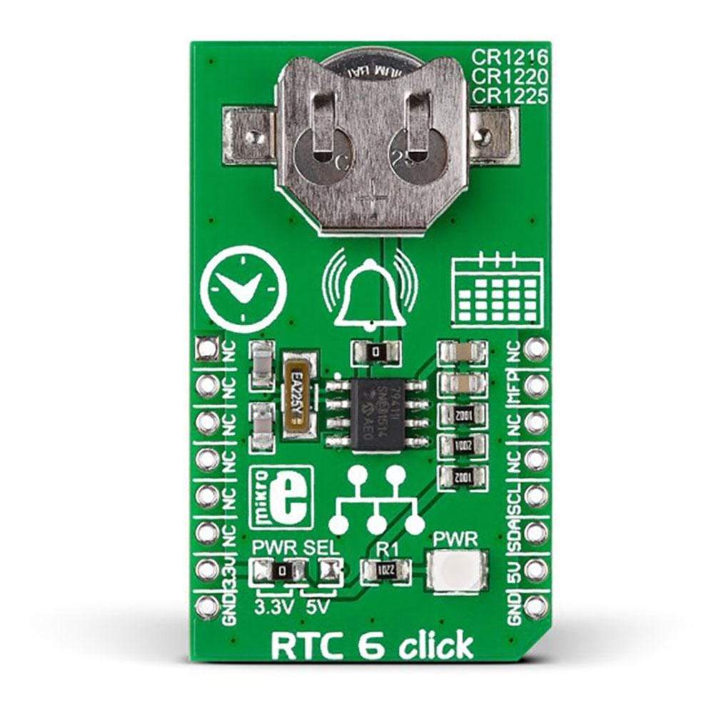
The RTC6 Click Board™ is based on the Microchip MCP79410 Real-Time Clock/Calendar IC with built-in 64 bytes of battery-backed SRAM an additional 1 Kbit of EEPROM. 64 bits of protected EEPROM requires an unlock sequence to be unlocked, which makes it suitable for storing a unique ID or other critical information. RTC6 Click Board™ tracks hours, minutes, seconds, days, months, years and weekdays, with leap year compensation until the year 2399. The clock frequency is derived from an on-board 32.768KHz crystal oscillator.
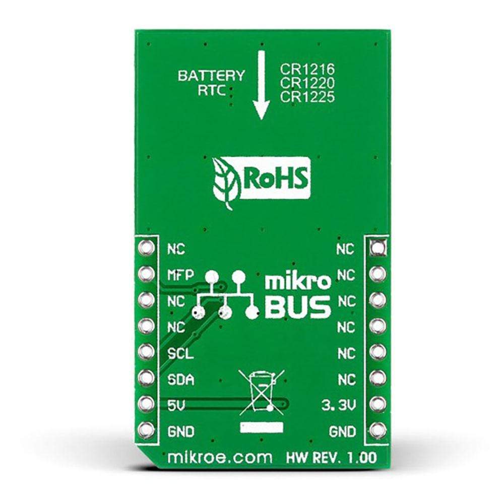
Backup power is supplied by a coin-cell Lithium battery. The RTC6 Click Board™ communicates with the target board MCU through the mikroBUS I2C interface (SCL, SDA) along with a multifunction pin (MFP, in place of default mikroBUS INT pin). The multifunctional pin (MFP) can be configured as an alarm, a square wave frequency output, or a general purpose output. The board is designed to use either a 3.3V or a 5V power supply.
RTC 6 Click Board
Frequently Asked Questions
Have a Question?
Be the first to ask a question about this.