


Mikroelektronika d.o.o.
DC Motor 3 Click Board™
DC Motor 3 Click Board™
SKU: MIKROE-2047
Couldn't load pickup availability
Overview
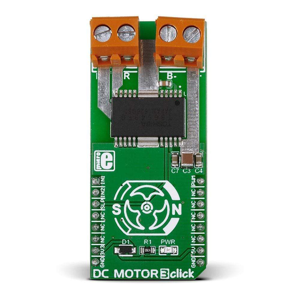
The DC Motor 3 Click Board™ is a MikroBUS add-on board with a Toshiba TB6549FG full-bridge driver for direct current motors. The IC can output currents of up to 3.5 A with 30V, making it suitable for high-power motors.
Downloads
The DC Motor 3 Click Board™ has two pairs of screw terminals are positioned on the top of the board. One is for bringing an external power supply; the other is for connecting a motor.
The Toshiba TB6549FG has four operating modes: clockwise, counter-clockwise, short brake and stop. The operating mode is configured through IN1 and IN2 pins. A separately controlled standby mode is also available.
For safety, the TB6549FG IC incorporates overcurrent protection and a thermal shutdown circuit.
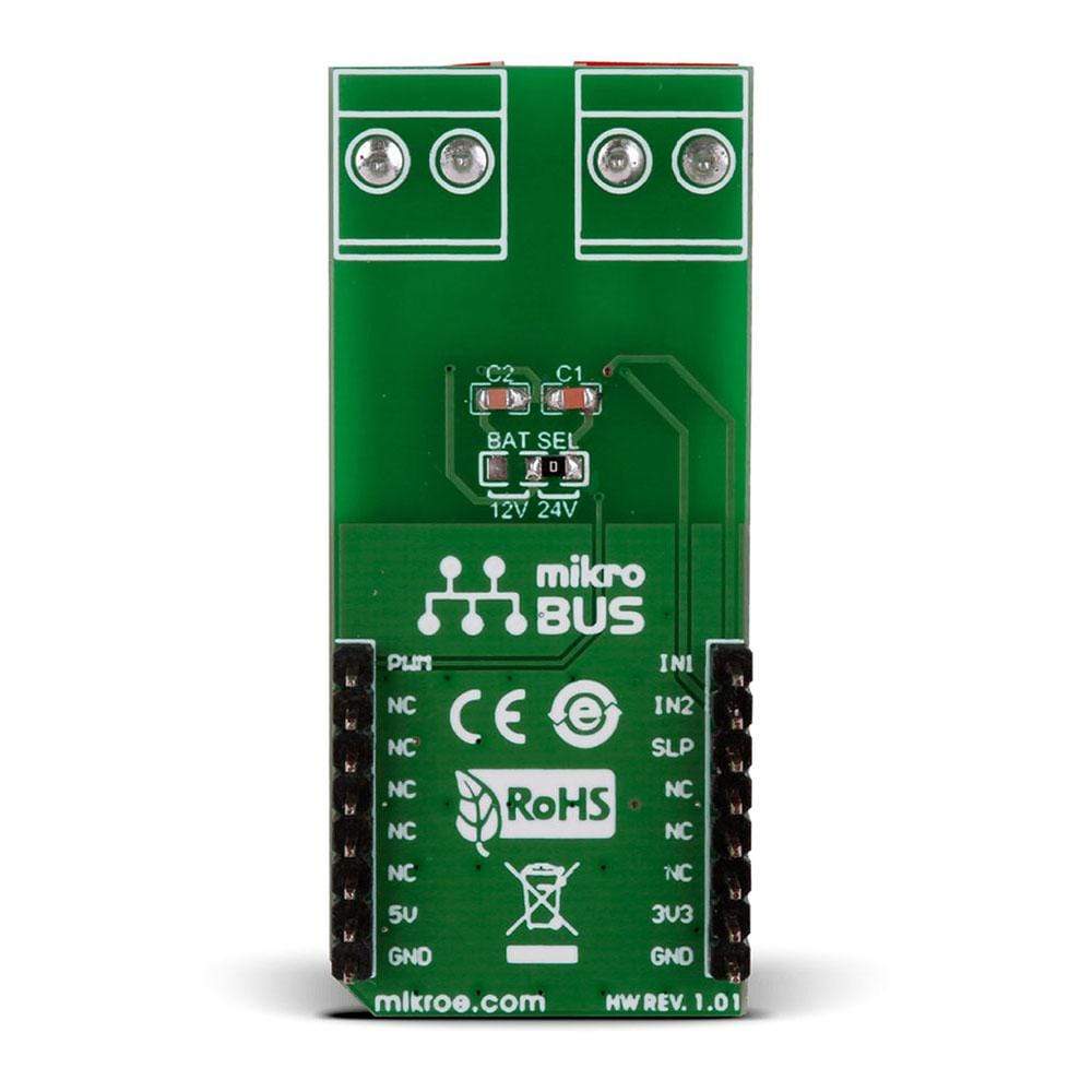
The DC Motor 3 Click Board™ communicates with the target MCU through the mikroBUS™ PWM pin, with additional functionality provided by IN1, IN2 and SLP pins (in place of default mikroBUS™ AN, RST and CS pins). Designed to use a 3.3 power supply only.
| General Information | |
|---|---|
Part Number (SKU) |
MIKROE-2047
|
Manufacturer |
|
| Physical and Mechanical | |
Weight |
0.025 kg
|
| Other | |
EAN |
8606018711178
|
Frequently Asked Questions
Have a Question?
Be the first to ask a question about this.