


Mikroelektronika d.o.o.
LED Driver 11 Click Board™
LED Driver 11 Click Board™
SKU: MIKROE-4757
Couldn't load pickup availability


Overview
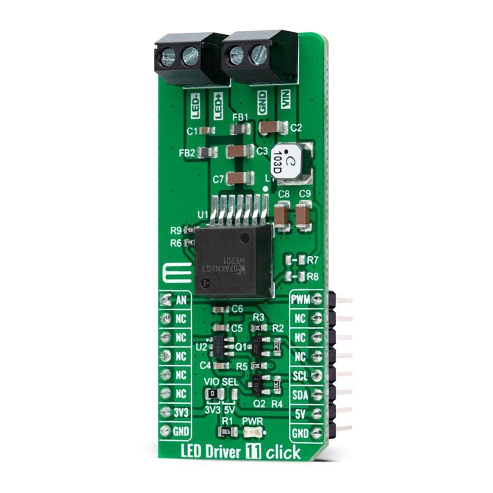
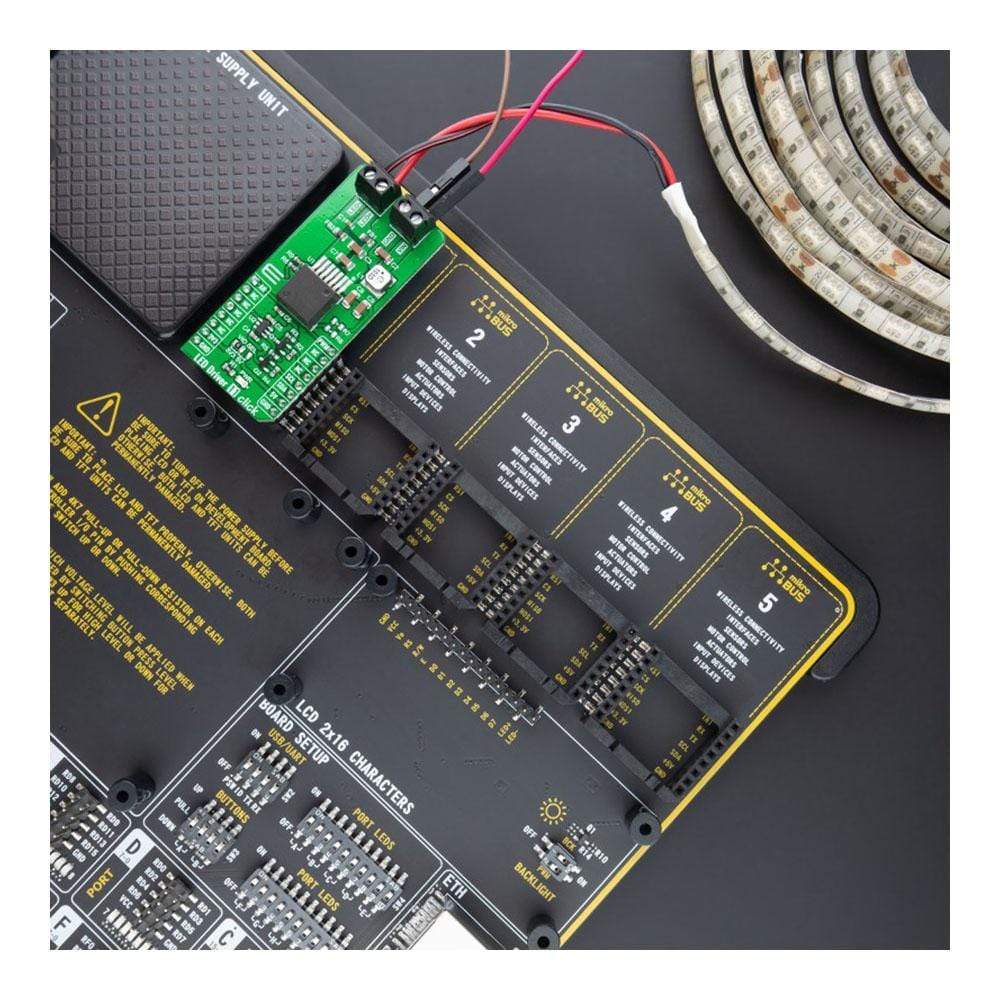
The LED Driver 11 Click Board™ is a compact add-on board that simplifies the control of multiple LEDs. This board features the WLMDU9456001JT (172946001), a fully integrated constant current LED driver with the buck switching regulator and inductor in a single package from Würth Elektronik. It offers high efficiency, delivers up to 450mA of LED current, and operates from 4.5V input voltage up to 60V, supporting up to 16 LEDs in series. It is designed for fast PWM dimming for no colour shift. This Click Board™ is suitable for colour mixing and backlight application for amusement products, LED status signalization, home automation projects, and many more.
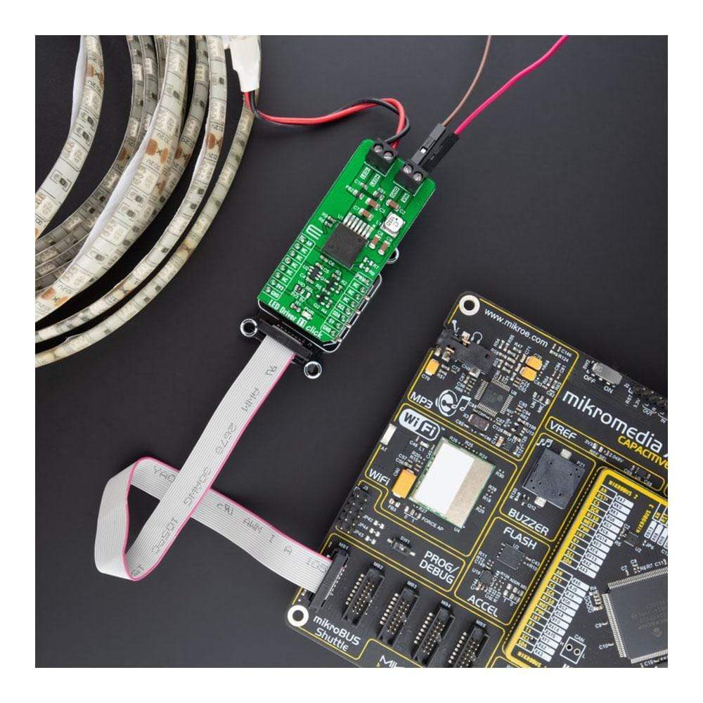
The The LED Driver 11 Click Board™ is supported by a mikroSDK compliant library, which includes functions that simplify software development. This Click Board™ comes as a fully tested product, ready to be used on a system equipped with the mikroBUS™ socket.
Downloads
How Does The LED Driver 11 Click Board™ Work?
The LED Driver 11 Click Board™ as its foundation uses the WLMDU9456001JT (172946001), a LED driver based on a non-synchronous floating buck regulator with integrated MOSFET, integrated diode, and a power inductor able to deliver both constant and pulsed currents from Würth Elektronik. It can provide an output current of up to 450mA at an output voltage from 4.5V to 60V limited by the input voltage of the module, which must be equal to or greater than the desired output voltage for proper operation. The WLMDU9456001JT also has integrated protection circuitry to guard against thermal overstress and electrical damage featuring thermal shutdown, input under-voltage lockout, and LED short-circuit protections.

The control loop is based on a current-mode control scheme with the fixed switching frequency, assuring accurate constant current regulation and good EMI performance. The MCP4726 obtains the LED current regulation, a 12-bit digital-to-analogue converter from Microchip, which can adjust the LED current up to 450mA. The MCP4726 also integrates EEPROM for storing DAC register and configuration bit values and communicates with the MCU through the I2C 2-Wire interface supporting Standard (100 kHz), Fast (400 kHz), and High-Speed (3.4 MHz) I2C modes. In addition, the WLMDU9456001JT features an integrated switch current limiting mechanism to prevent the LEDs from being overdriven.
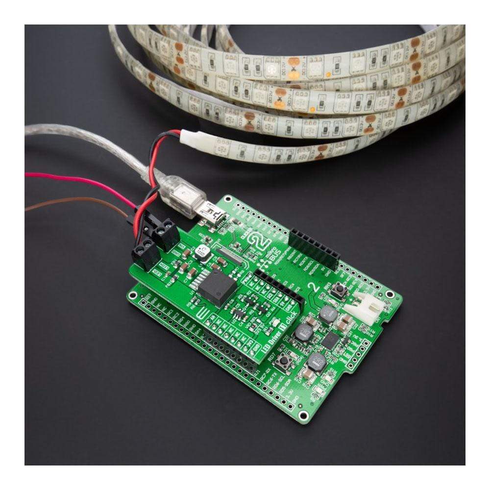
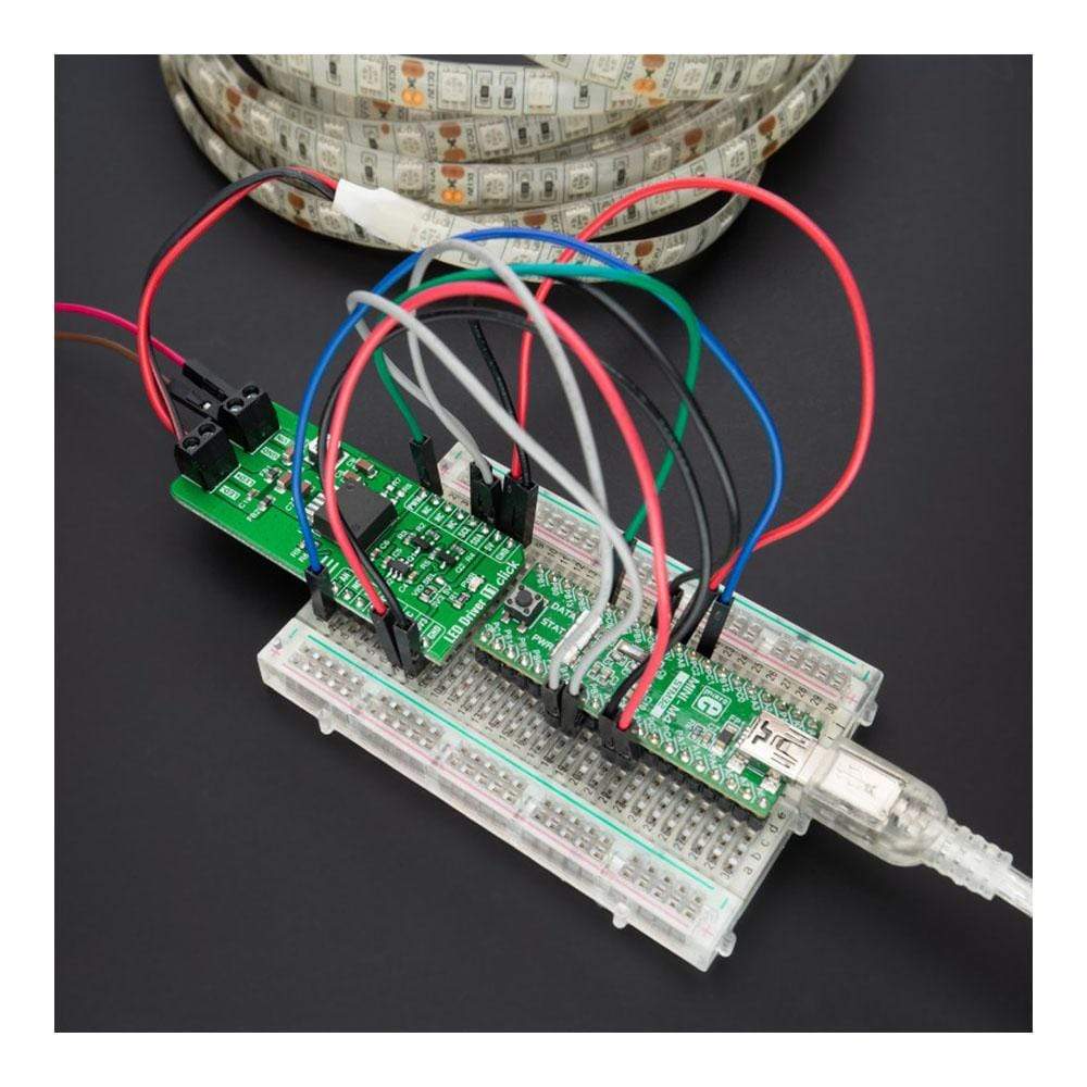
The LED Driver 11 Click Board™ offers two ways to implement the LED dimming: analogue dimming and PWM dimming. Both methods control the average current flowing through the LEDs. The analogue dimming can be achieved by adjusting the LED current by using an external voltage source on the VIN terminal, while the PWM dimming is implemented by direct control of the dimming control signal routed to the PWM pin on the mikroBUS™ socket. Applying a logic level PWM signal to the WLMDU9456001JT DIM pin, the user can control the brightness of the LED string. The maximum frequency of the PWM dimming signal should not exceed a frequency of 80kHz.
Additionally, the under-voltage lockout voltage divider realized with R7 and R8 is not placed. This option can be used if a particular input voltage should be present before turn on or to ensure safe turn-off of the output voltage in the event of an input voltage dip.
The LED Driver 11 Click Board™ can operate with both 3.3V and 5V logic voltage levels selected via the VCC SEL jumper. This way, it is allowed for both 3.3V and 5V capable MCUs to use the communication lines properly. However, the Click board™ comes equipped with a library containing easy-to-use functions and an example code that can be used, as a reference, for further development.
SPECIFICATIONS
| Type | LED Drivers |
| Applications | Can be used for colour mixing and backlight application for amusement products, LED status signalization, home automation projects, and many more |
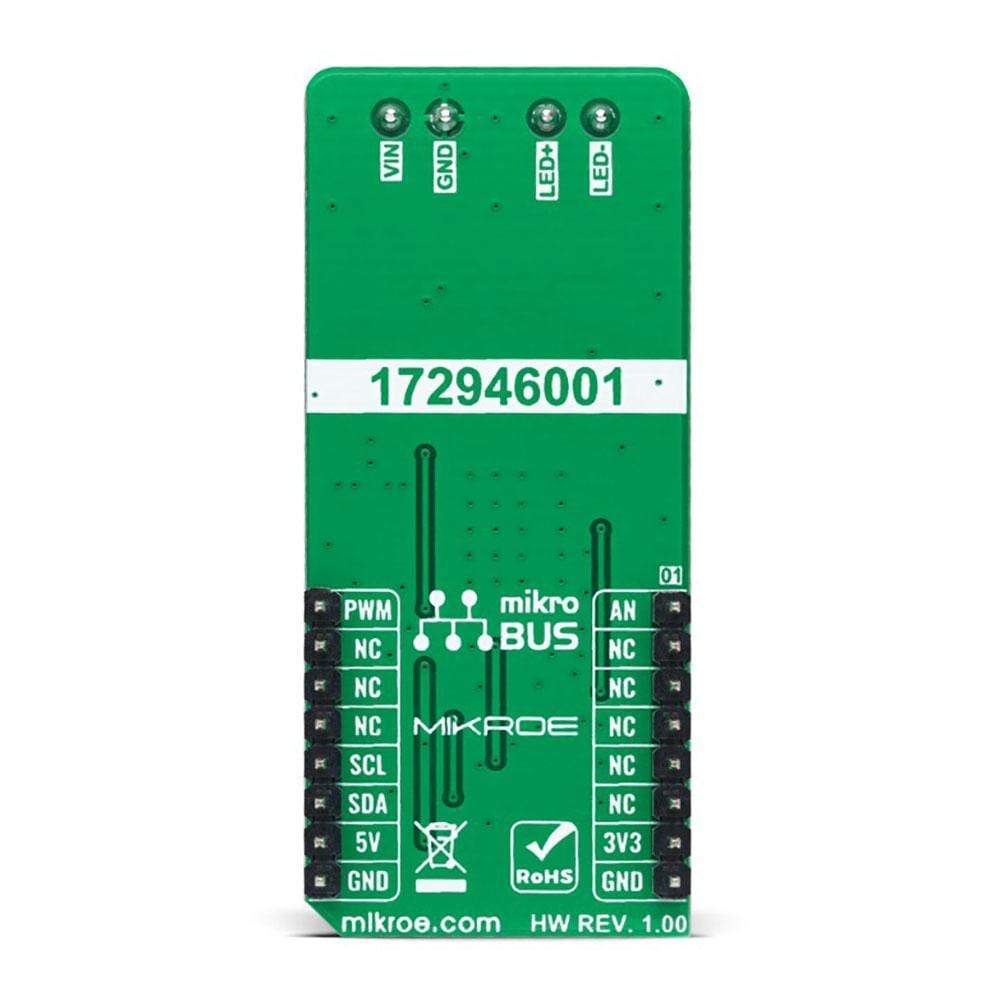
| On-board modules | WLMDU9456001JT (172946001) - fully integrated constant current LED driver with the buck switching regulator and inductor in a single package from Würth Elektronik |
| Key Features | Adjustable LED current, wide input/output voltage range, PWM/Analog dimming, an integrated shielded inductor, onboard protection circuitry, and more |
| Interface | Analog,I2C,PWM |
| Compatibility | mikroBUS |
| Click board size | L (57.15 x 25.4 mm) |
| Input Voltage | 3.3V or 5V, External |
PINOUT DIAGRAM
This table shows how the pinout on LED Driver 11 Click corresponds to the pinout on the mikroBUS™ socket (the latter shown in the two middle columns).
| Notes | Pin | Pin | Notes | ||||
|---|---|---|---|---|---|---|---|
| Analog Signal | AN | 1 | AN | PWM | 16 | PWM | PWM Signal |
| NC | 2 | RST | INT | 15 | NC | ||
| NC | 3 | CS | RX | 14 | NC | ||
| NC | 4 | SCK | TX | 13 | NC | ||
| NC | 5 | MISO | SCL | 12 | SCL | I2C Clock | |
| NC | 6 | MOSI | SDA | 11 | SDA | I2C Data | |
| Power Supply | 3.3V | 7 | 3.3V | 5V | 10 | 5V | Power Supply |
| Ground | GND | 8 | GND | GND | 9 | GND | Ground |
ONBOARD SETTINGS AND INDICATORS
| Label | Name | Default | Description |
|---|---|---|---|
| LD1 | PWR | - | Power LED Indicator |
| JP1 | VIO SEL | Left | Logic Level Voltage Selection 3V3/5V: Left position 3V3, Right position 5V |
| R7-R8 | R7-R8 | Unpopulated | Under-voltage Lockout Voltage Divider Resistors |
LED DRIVER 11 CLICK ELECTRICAL SPECIFICATIONS
| Description | Min | Typ | Max | Unit |
|---|---|---|---|---|
| Supply Voltage VCC | 3.3 | - | 5 | V |
| External Supply Voltage VIN | 4.5 | - | 60 | V |
| Nominal LED Current | - | - | 450 | mA |
| Operating Temperature Range | -40 | +25 | +85 | °C |
| General Information | |
|---|---|
Part Number (SKU) |
MIKROE-4757
|
Manufacturer |
|
| Physical and Mechanical | |
Weight |
0.02 kg
|
| Other | |
EAN |
8606027383472
|
Frequently Asked Questions
Have a Question?
Be the first to ask a question about this.