Overview
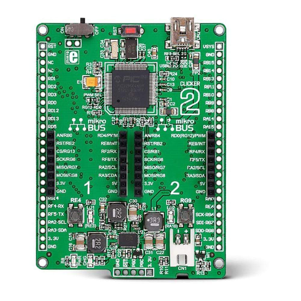
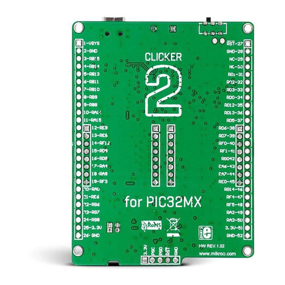
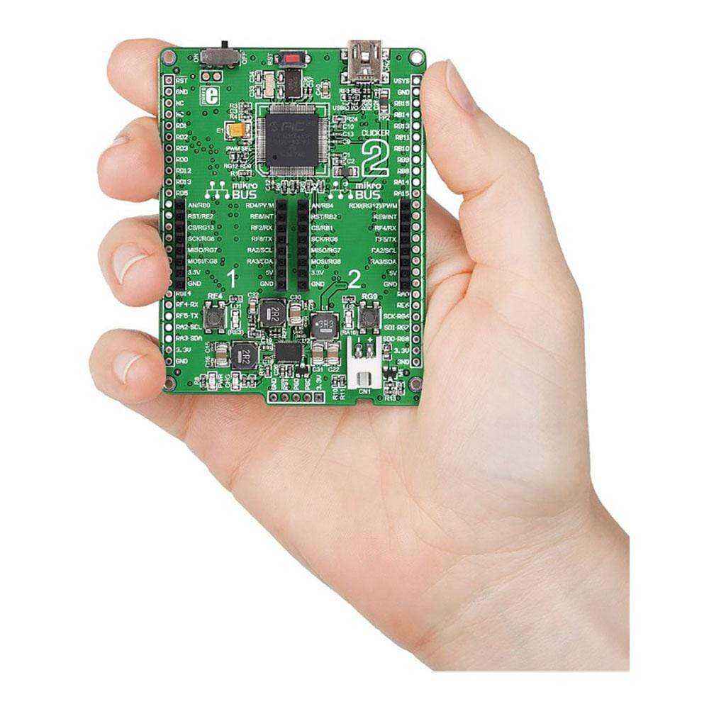
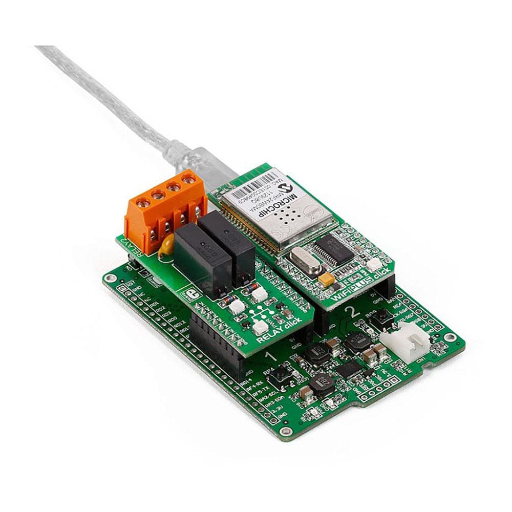
Blend different functionalities together and quickly build new and original gadgets using the Clicker 2 Board™ for PIC32MX. The Click Board™ two-seater for PIC32MX is a compact development board driven by a 32-bit PIC32MX460F512L MCU from Microchip, operates at 80 MHz/105DMIPS, and has 512+12KB of program memory and 32KB of RAM. This Clicker 2 Board™ board includes two MikroBUS sockets that allow the user to plug in any two add-on Click Boards™ with unique functionalities and features. The board also has two indicator LEDs, two general-purpose buttons, a reset button, a USB Mini-B connector, a li-polymer battery connector, and an on/off switch. To assist in interfacing with external electronics, a MikroProg connector and a 2x26 pinout is provided.
The user can supply power to the Clicker 2 Board™ for PIC32MX board with either a Mini-B USB cable or using a Li-Polymer battery, via an on-board battery connector. It comes preprogrammed with a fast USB HID bootloader, which enables the user to load code into it without requiring an external programmer. However, the user can also program the MCU using an external programmer using onboard pads for installing a header compatible with the MikroProg for PIC.
An LTC3586-1 power management IC allows charging of a connected battery via USB and delivers 3.3V or 5V to the add-on boards. The MikroBUS host connectors each consist of two 1'.
Downloads
PIC32MX460F512L Microcontroller
The Clicker 2 Board™ for PIC32MX board features a 32-bit MIPS M4K Core PIC32MX460F512L microcontroller with 512KB of Flash and 32KB RAM. It has an integrated full speed USB 2.0. support and is rich with on-chip peripherals.
Microcontroller Programming
The microcontroller used can be programmed in three ways: Using USB HID mikroBootloader; using external mikroProg for PIC32MX programmer; Using external ICD2/3 programmer.
Power Supply
The Clicker 2 Board™ for PIC32MX can be connected to the power supply in two ways: USB and Battery. When using a Mini-B USB cable, the voltage regulators provide the appropriate voltage levels to each on-board component. The green LED denotes the presence of power supply. When using a Li-Polymer battery, the on-board battery charger circuit allows user to charge the battery over USB connection. The red LED denotes that the battery is in charging state.
Frequently Asked Questions
Have a Question?
Be the first to ask a question about this.

