


Mikroelektronika d.o.o.
CAN FD 4 Click Board™
CAN FD 4 Click Board™
SKU: MIKROE-4107
Couldn't load pickup availability
Overview
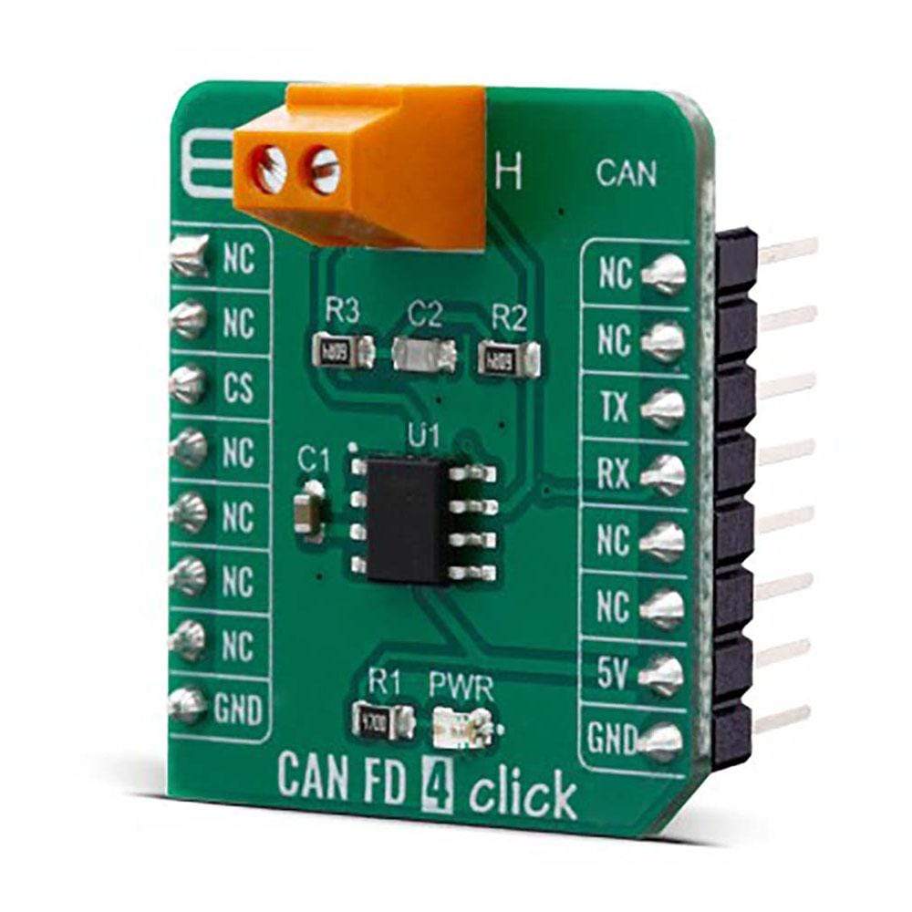
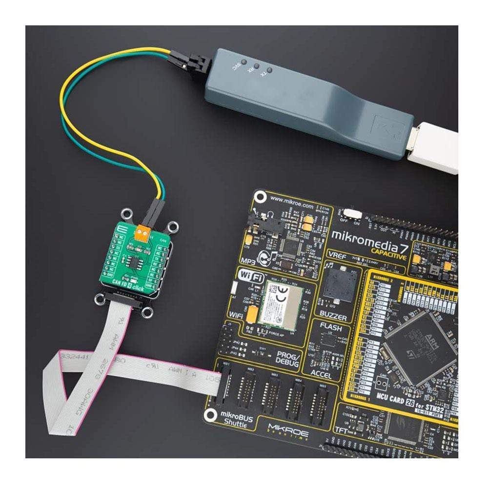
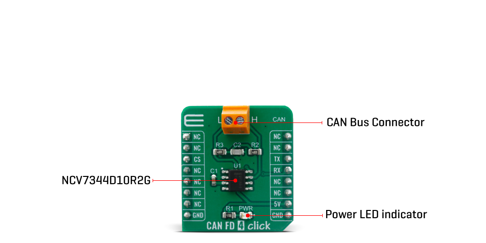
The CAN FD 4 Click Board™ features the NCV7344D10R2G, a Controller Area Network (CAN) transceiver, from ON Semiconductor. This Click Board™ provides differential transmit capability to the bus and differential receive capability to the CAN controller.
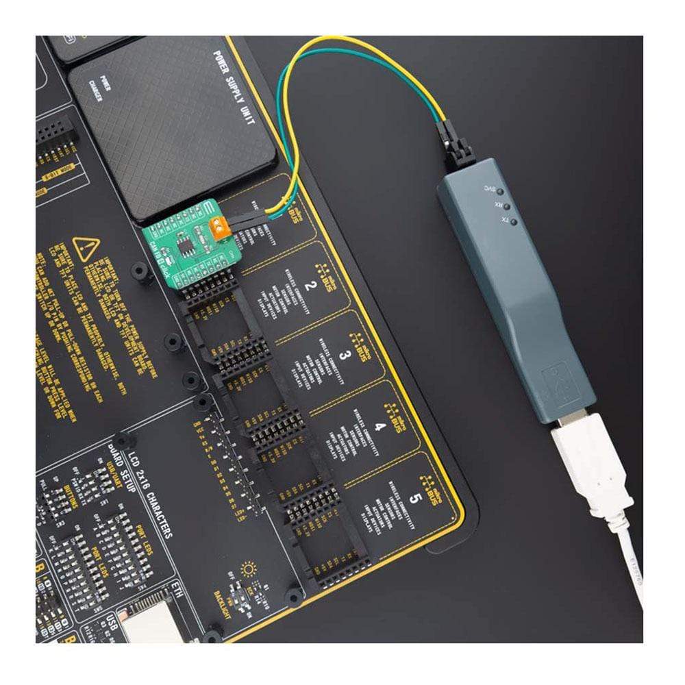
The CAN FD 4 Click Board™ can be used for various applications such as automotive and industrial networks.
Downloads
How Does The CAN FD 4 Click Board™ Work?
The CAN FD 4 Click Board™ is based on the NCV7344D10R2G, is a complete CAN protocol controller and the physical bus, from ON Semiconductor. The Click board™ guarantees additional timing parameters to ensure robust communication at data rates beyond 1 Mbps to cope with CAN flexible data rate requirements (CAN FD). These features make the CAN FD 4 Click an good choice for all types of high speed - controller area network (HS−CAN) networks.
The CAN FD 4 Click Board™ provides two operation modes, these modes are selectable pin CS.
First option is normal mode (when CS pin is LOW), where the transceiver is able to communicate via the bus line.The signals are transmitted and received to the CAN controller via the pins TxD and RxD. The slopes on the bus lines outputs are optimized to give low EME. Second option is when CS pin is HIGH, and the CAN FD 4 Click is in Standby mode. In standby mode both the transmitter and receiver are disabled and a very low−power differential receiver monitors the bus lines for CAN bus activity.When a wake−up request is detected by the low−power differential receiver, the signal is first filtered and then verified as a valid wake signal after a time period of twake_filt, the RxD pin is driven low by the transceiver (following the bus) to inform the controller of the wake−up request.
High speed CAN (HS CAN) is a serial bus system that connects microcontrollers, sensors and actuators for realtime control applications. Compatible with ISO 11898-2 (2016) describes the use of the Controller Area Network (CAN) within road vehicles. According to the 7-layer OSI reference model the physical layer of a HS CAN bus system specifies the data transmission from one CAN node to all other available CAN nodes within the network. The CAN transceiver is part of the physical layer.
The CAN FD 4 Click Board™ is designed to be operated only with 5V logic level. A proper logic voltage level conversion should be performed before the Click board™ is used with MCUs with logic levels of 3.3V.
SPECIFICATIONS
| Type | CAN,CAN FD |
| Applications | HS CAN networks in automotive applications and HS CAN networks in industrial applications |
| On-board modules | NCV7344D10R2G, Controller Area Network (CAN) transceiver from ON Semiconductor. |
| Key Features | Automotive and Industrial Networks |
| Interface | UART |
| Compatibility | mikroBUS |
| Click board size | S (28.6 x 25.4 mm) |
| Input Voltage | 5V |
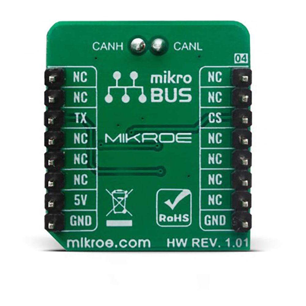
PINOUT DIAGRAM
This table shows how the pinout for the CAN FD 4 Click Board™ corresponds to the pinout on the mikroBUS™ socket (the latter shown in the two middle columns).
| Notes | Pin | Pin | Notes | ||||
|---|---|---|---|---|---|---|---|
| NC | 1 | AN | PWM | 16 | NC | ||
| NC | 2 | RST | INT | 15 | NC | ||
| Chip Select | CS | 3 | CS | RX | 14 | TX | UART Transmit |
| NC | 4 | SCK | TX | 13 | RX | UART Receive | |
| NC | 5 | MISO | SCL | 12 | NC | ||
| NC | 6 | MOSI | SDA | 11 | NC | ||
| NC | 7 | 3.3V | 5V | 10 | 5V | Power Supply | |
| Ground | GND | 8 | GND | GND | 9 | GND | Ground |
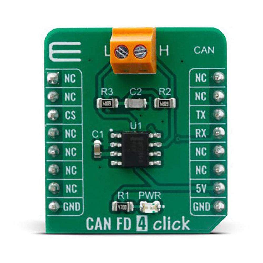
ONBOARD SETTINGS AND INDICATORS
| Label | Name | Default | Description |
|---|---|---|---|
| LD1 | PWR | - | Power LED Indicator |
| General Information | |
|---|---|
Part Number (SKU) |
MIKROE-4107
|
Manufacturer |
|
| Physical and Mechanical | |
Weight |
0.018 kg
|
| Other | |
EAN |
8606018717408
|
Frequently Asked Questions
Have a Question?
Be the first to ask a question about this.