Overview
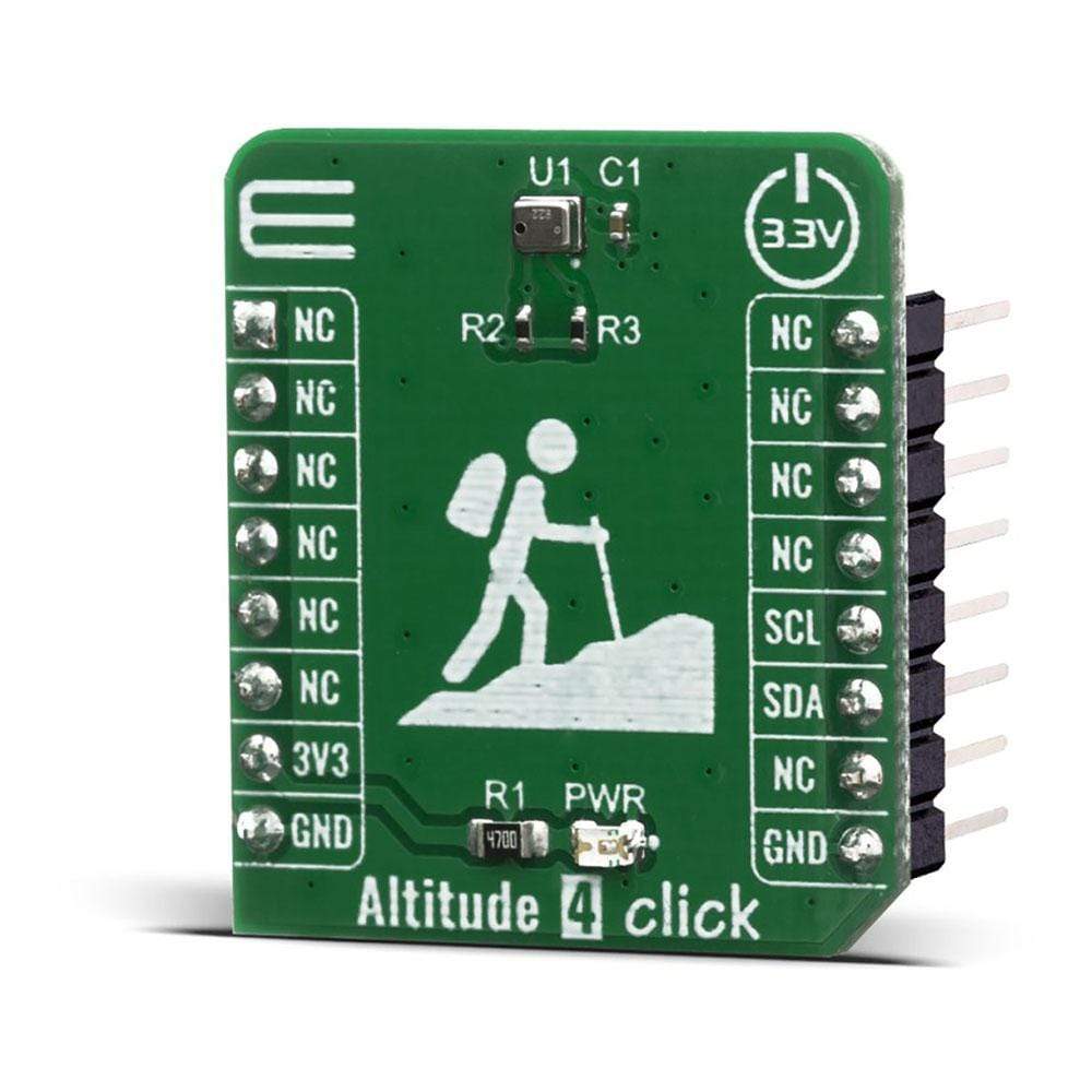
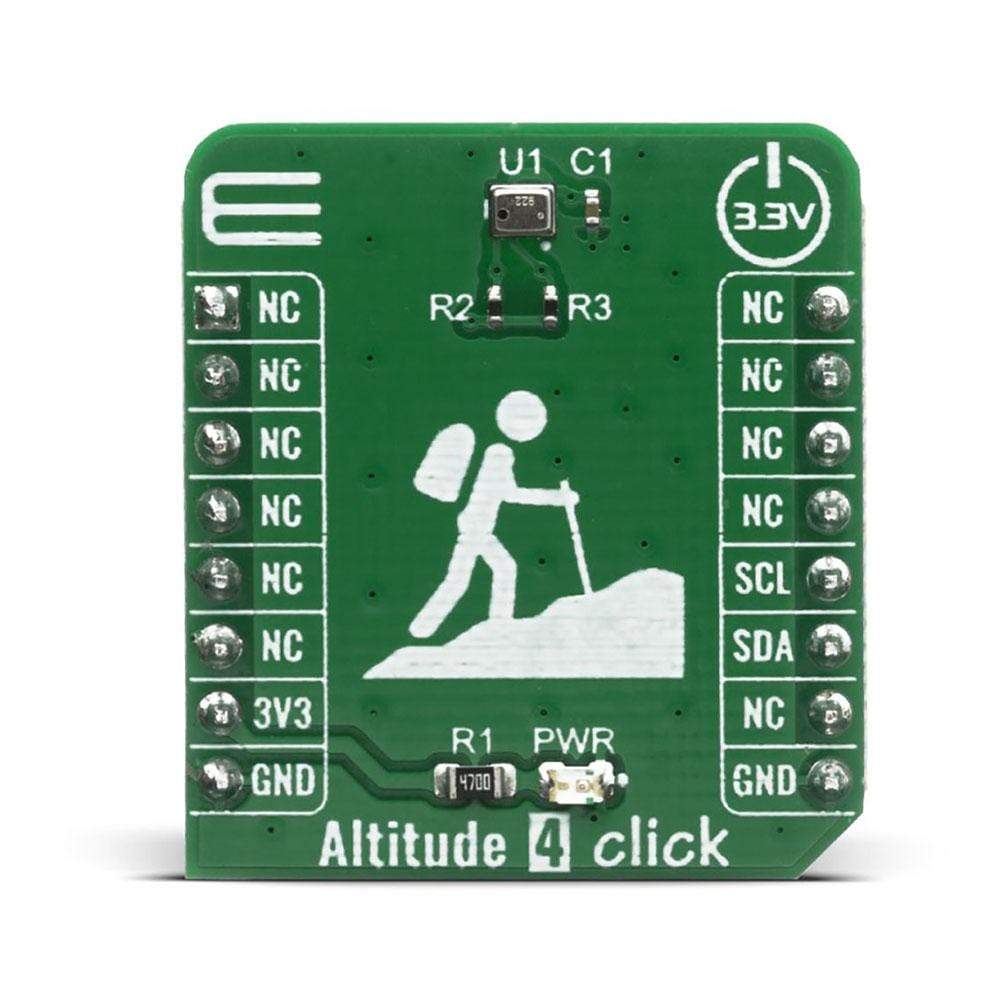
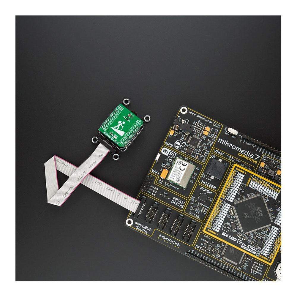
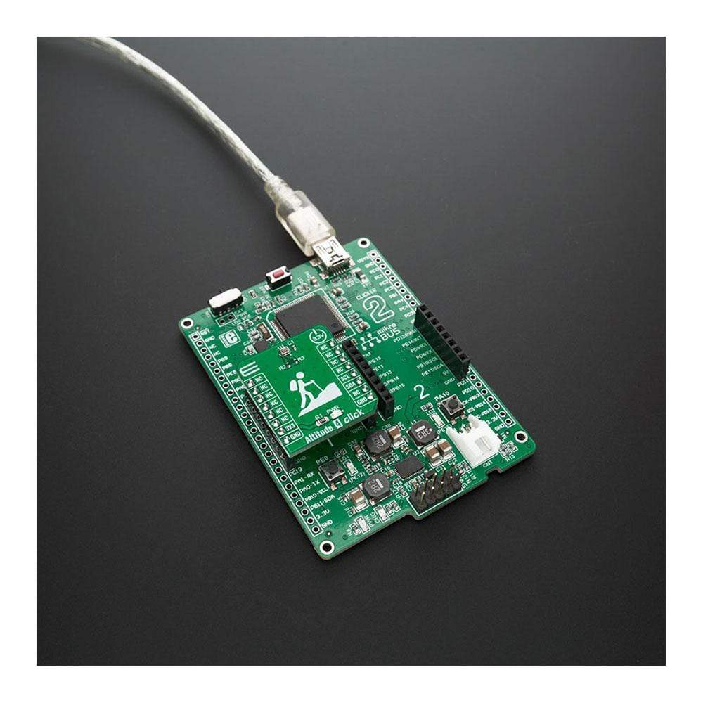
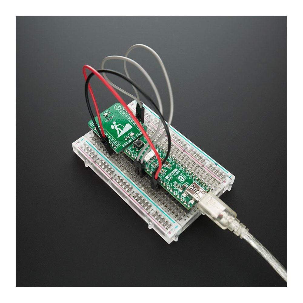
The Altitude 4 Click Board™ introduces an absolute pressure sensor with digital output for low-cost applications labelled as NPA-201. Altitude 4 Click Board™ employs a MEMS pressure sensor with a signal-conditioning IC to provide accurate pressure measurements from 260 to 1260 mBar. Measurement values are provided at the digital output pins through an I2C interface. This sensor provides NPA-201 Digital Output Absolute Pressure Sensor provides low power consumption and compact size, making it ideal for battery-powered and mobile applications or any application where size is a constraint.
In today’s growing market for portable electronics and wearables with multiple parameters being measured, many applications require an accurate measurement of barometric pressure to determine factors such as altitude.
Downloads
How Does The Altitude 4 Click Board™ Work?
The Altitude 4 Click Board™ uses the NovaSensor NPA-201 , a digital output absolute pressure sensor that provides low power consumption and compact size. With a miniature 2.0x2.5x1.0mm HCLGA package, it is ideally suited for portable electronics and space-constrained applications. Low power consumption of 20nA during Sleep Mode is ideal for battery and other low-power applications. A wide operating temperature range from -40°C to +85°C fits well with demanding environmental requirements. Equipped with a MEMS pressure sensor with a signal-conditioning IC, Click Board™ provides accurate measurements from 260 to 1260 mBar. Thanks to ASIC's inner structure, the measurement results are not only compensated but also temperature corrected and calibrated with an internal sensor. Digital compensation of the signal offset, sensitivity, temperature and non-linearity is accomplished via an 18-bit internal digital signal processor (DSP) running a correction algorithm. Calibration coefficients are stored on-chip in highly reliable, nonvolatile, multiple-time programmable (MTP) memory. The measurement and corrected bridge values provided at the digital output of the chip are routed to Mikrobus I2C reserved pins SCL and SDA.
.jpg)
This device offers the possibility to change the I2C slave address. NPA-201 sensors are supplied with the slave address set to default value. This address is stored within the sensor's internal EEPROM memory. By modifying the specific bits, the sensor is put into a special programming mode following the instruction sent by the master in order to change the slave address. Before attempting this procedure, users should familiarise themselves with the datasheet provided by the manufacturer. Care must be taken to ensure that only the specified data bits are changed. Writing data to other locations may cause the sensor to become permanently unusable. The address can be changed up to 3 times, after which no further memory changes are possible.
Altitude can be determined based on the measurement of atmospheric pressure. The greater the altitude, the lower the pressure. A pressure altimeter is mostly used in aircraft vehicles but can be also found in skydiver's wrist-mounted versions for similar purposes. Hikers and mountain climbers use wrist-mounted or hand-held altimeters, in addition to other navigational tools such as a map, magnetic compass, or GPS receiver.

The following calculation expresses the hypsometric equation where P 0 is the pressure at sea level, P is the measured pressure, h is elevation or altitude of measured data and T is the measured temperature in Celsius. The calculation for altitude is based on the difference between current atmospheric pressure and pressure at sea level. Every 8.8 meters atmospheric pressure drops by 1mBar. If the altitude is more than 11km high above sea level, the hypsometric formula cannot be applied because the temperature lapse rate (0.0065 °C/m) varies considerably with altitude.
The Altitude 4 Click Board™ uses the I2C communication interface and is designed to be operated only with a 3.3V logic level. A proper logic voltage level conversion should be performed before the Click board™ is used with MCUs with different logic levels.
Specifications
| Type | Altitude,Pressure |
| Applications | Pressure sensor for mobile devices, indoor and outdoor navigation, enhancement of GPS navigation, altimeter and barometer for portable devices, weather station equipment, leisure and sports, Hard Disk Drive (HDD), weather forecast. |
| On-board modules | The Altitude 4 Click Board™ uses the NPA-201 IC, an absolute pressure sensor with digital output for low-cost applications, from Amphenol Advanced Sensors. |
| Key Features | Barometric pressure sensing applications for sports activity identification, mobile indoor/outdoor navigation, altitude-hold and stabilization in drones, and other |
| Interface | I2C |
| Compatibility | mikroBUS |
| Click board size | S (28.6 x 25.4 mm) |
| Input Voltage | 3.3V |
Pinout Diagram
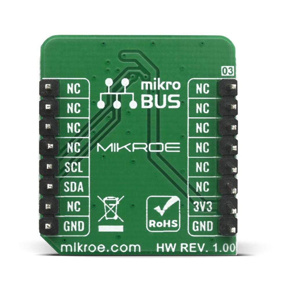
This table shows how the pinout of the Altitude 4 Click Board™ corresponds to the pinout on the mikroBUS™ socket (the latter shown in the two middle columns).
| Notes | Pin |  |
Pin | Notes | |||
|---|---|---|---|---|---|---|---|
| NC | 1 | AN | PWM | 16 | NC | ||
| NC | 2 | RST | INT | 15 | NC | ||
| NC | 3 | CS | RX | 14 | NC | ||
| NC | 4 | SCK | TX | 13 | NC | ||
| NC | 5 | MISO | SCL | 12 | SCL | I2C Clock | |
| NC | 6 | MOSI | SDA | 11 | SDA | I2C Data | |
| Power Supply | 3.3V | 7 | 3.3V | 5V | 10 | NC | |
| Ground | GND | 8 | GND | GND | 9 | GND | Ground |
ONBOARD SETTINGS AND INDICATORS
| Label | Name | Default | Description |
|---|---|---|---|
| LD1 | PWR | - | Power LED Indicator |
ALTITUDE 4 CLICK ELECTRICAL Specifications
| Description | Min | Typ | Max | Unit |
|---|---|---|---|---|
| Supply Voltage | -0.4 | 3.3 | 3.63 | V |
| Pressure Accuracy | -1 | - | 1 | %FSO |
| Full Accuracy Temperature | -30 | 80 | °C | |
| Current Consumption |
- - |
35¹ 20 |
- 250² |
µA nA |
| Operating Pressure Range | 260 | 1260 | mBar |
Remark:
- Read time = 500ms
- Sleep State, Idle Current, <85 °C
| General Information | |
|---|---|
Part Number (SKU) |
MIKROE-4127
|
Manufacturer |
|
| Physical and Mechanical | |
Weight |
0.018 kg
|
| Other | |
Country of Origin |
|
HS Code Customs Tariff code
|
|
EAN |
8606018717477
|
Warranty |
|
Frequently Asked Questions
Have a Question?
Be the first to ask a question about this.


