


OMICRON-Lab
OMICRON Lab B-WIC - Impedanzprüfvorrichtung für bedrahtete Komponenten
OMICRON Lab B-WIC - Impedanzprüfvorrichtung für bedrahtete Komponenten
SKU: P0005760
Verfügbarkeit für Abholungen konnte nicht geladen werden


Overview
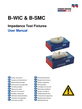
The OMICRON Lab B-WIC is an impedance test fixture that turns a Bode 100 into an LCR meter or impedance analyser for wired (through-hole) components. Usable range 1 Hz to 50 MHz, recommended impedance range 20 mΩ to 600 kΩ, gold-plated electrodes with around 0.5 mΩ contact resistance, leads up to 1.8 mm diameter. A B-CAL calibration board for Short and Load calibration is included. For surface-mount parts, OMICRON Lab offers the B-SMC.
Downloads
Quick Start Guides
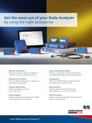
The OMICRON Lab B-WIC is an impedance test fixture for wired (through-hole) components that turns a Bode 100 into an LCR meter or impedance analyser, usable from 1 Hz to 50 MHz over a recommended impedance range of 20 mΩ to 600 kΩ. Gold-plated, spring-loaded electrodes take leads up to 1.8 mm in diameter with a contact resistance of around 0.5 mΩ. Hardware and power electronics engineers use it for RLC-Q measurement of leaded resistors, capacitors and inductors across frequency.
RLC-Q Measurement From 1 Hz to 50 MHz
The B-WIC is optimised for RLC-Q measurement of common passive components. OMICRON Lab specifies a usable frequency range of 1 Hz to 50 MHz and recommends the fixture for impedances from 20 mΩ to 600 kΩ. Inside is a resistive measurement bridge with a voltage divider and a current shunt: CH1 receives a signal proportional to the DUT voltage and CH2 a signal proportional to the DUT current. The Bode Analyzer Suite runs it in the Impedance Adapter measurement mode.
Gold-Plated Electrodes for Wired Components
The electrodes are 24 mm long and accept DUT wires up to 1.8 mm in diameter, with a minimum clearance of 3 mm between wires. Contact resistance is around 0.5 mΩ, which matters at the low end of the impedance range, so clean the gold-plated contacts before Short calibration and low-value measurements. Keep leads short. Extra lead length and large DUTs add stray capacitance and measurement error.
Impedance Test Fixture Setup and Calibration with the Bode 100
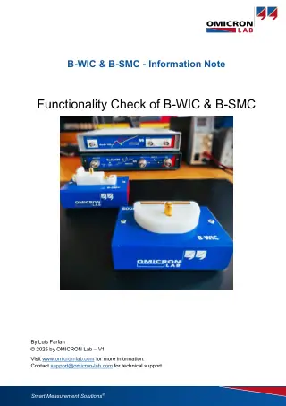
Three BNC sockets connect the fixture to the Bode 100: SOURCE from the analyser output, CH1 and CH2 to the matching inputs. Open, Short and Load calibration is required before measuring. Open is run with no DUT fitted; Short and Load use the supplied B-CAL calibration board, inserted short side then load side. Accuracy depends on these calibration elements and on clean contacts. OMICRON Lab characterised typical relative accuracy against an Agilent E4980A precision LCR meter at 10 Hz receiver bandwidth, and publishes the chart in the B-WIC and B-SMC user manual.
Specifications
| Usable frequency range | 1 Hz to 50 MHz |
|---|---|
| Recommended impedance range | 20 mΩ to 600 kΩ |
| Measurement principle | Resistive bridge (voltage divider and current shunt), CH1 voltage, CH2 current |
| Connectors | BNC sockets: SOURCE, CH1, CH2 (outer conductor connected to housing) |
| DUT contacts | Gold-plated electrodes with spring mechanics |
| Contact resistance | Approx. 0.5 mΩ |
| Max. DUT wire diameter | 1.8 mm |
| Min. DUT wire spacing | 3 mm |
| Electrode length | 24 mm |
| Dimensions | 100.5 x 68.2 x 55.5 mm (including connectors) |
| Weight | 0.16 kg |
| Operating temperature | +5 °C to +40 °C |
| Storage temperature | -35 °C to +60 °C |
| Relative humidity | 20% to 80%, non-condensing |
| Safety | SELV device (IEC 60950), protection class III |
| Compliance | CE, RoHS |
Limitations
- The analyser is not included. OMICRON Lab states the B-WIC is to be used only in conjunction with the Bode 100. Its B-WIC documentation does not cover the Bode 500, so ask us before ordering for a Bode 500 setup.
- Do not apply external voltages or currents. No DC bias rating is published.
- OMICRON Lab publishes a typical relative accuracy chart, not a guaranteed accuracy figure, and states the accuracy rating can change without notice.
- For surface-mount parts, choose the B-SMC, which takes DUTs up to 9.5 mm long and 7.5 mm wide.
Impedance Test Fixture Comparison
| Feature | B-WIC | B-SMC |
|---|---|---|
| Component type | Wired (through-hole) | Surface-mount |
| DUT limits | Wire diameter up to 1.8 mm, spacing min. 3 mm | Up to 9.5 mm long, 7.5 mm wide |
| Usable frequency range | 1 Hz to 50 MHz | 1 Hz to 50 MHz |
| Recommended impedance range | 20 mΩ to 600 kΩ | 20 mΩ to 600 kΩ |
| Weight | 0.16 kg | 0.13 kg |
| Price | £650 | £650 |
Typical Applications
Inductance and Q of leaded inductors and chokes swept up to 50 MHz. Capacitance and ESR of through-hole capacitors, using the 20 mΩ low end of the recommended range. Impedance against frequency of leaded resistors, to see where parasitic inductance or capacitance takes over.
The B-WIC suits engineers who already own a Bode 100 and need repeatable impedance measurements on leaded passives without building their own fixture.
What's Included
- B-WIC impedance test fixture
- B-CAL calibration board (1 pc.)
The OMICRON Lab B-WIC is £650 ex VAT. If you also need the analyser, contact us for a formal quotation covering the Bode 100 and fixture. See all vector network analyser accessories in our range.
Frequently Asked Questions
Does the B-WIC Work with the Bode 500?
OMICRON Lab's B-WIC documentation names only the Bode 100, and the user manual says to use the fixture only in conjunction with the Bode 100. The Bode 500 also has N-type connectors where the B-WIC uses BNC. Contact us before ordering if your analyser is a Bode 500.
Answered by John Legg, Director, Debug Store
Do I Need to Buy Calibration Standards?
No. A B-CAL calibration board ships with the B-WIC and provides the Short and Load references; Open needs no standard. A spare B-CAL-3 Calibration Board Set is available at £105.
Answered by John Legg, Director, Debug Store
Last reviewed: 30 October 2026
Sources (2 manufacturer pages)
| Ordering information | |
|---|---|
| Part number (SKU) | P0005760 |
| Manufacturer | OMICRON-Lab |
| EAN | 5055383623242 |
- Warranty: 12 Monate
Questions and Answers
No questions have been asked about this product yet. Ask our engineers below and we'll reply by email.