
ZeroPlus Technology Co Ltd
Zeroplus Protocol Simulator Board A - 46 Protocol Test Generator
Zeroplus Protocol Simulator Board A - 46 Protocol Test Generator
SKU: PROT-SIM-A
Couldn't load pickup availability
Key Features
Overview
Downloads
Why Engineers Choose The Zeroplus Protocol Simulator Board A - 46 Protocol Test Generator
Protocol Validation
Development Efficiency
Educational Training
Professional Protocol Simulation for Logic Analyser Testing
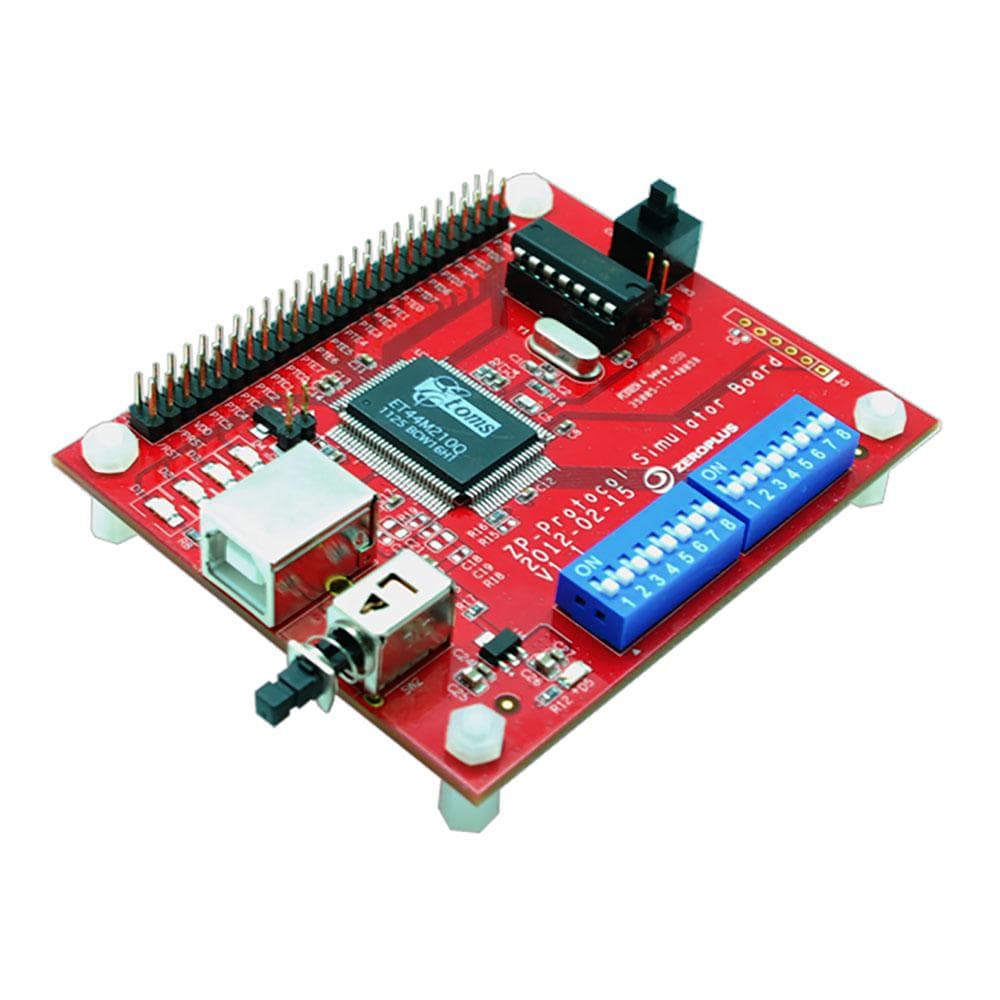
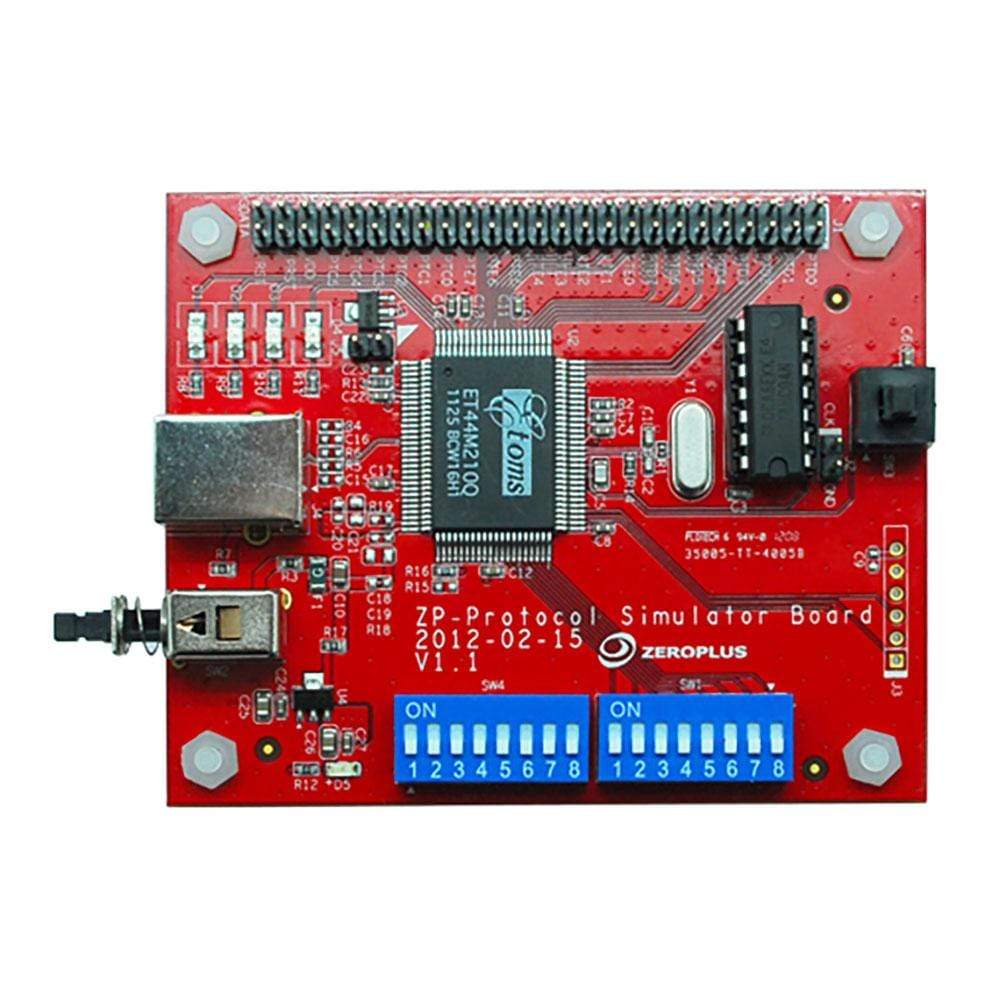
The Zeroplus Protocol Simulator Board A serves as a comprehensive test signal generator designed specifically for logic analyser validation and embedded system debugging. This compact PCB generates authentic protocol data packets across 46 different communication standards, enabling engineers to test and validate their logic analyser setups without requiring live system connections.
Complete Supported Protocol List
The Protocol Simulator Board A supports a comprehensive range of communication protocols covering embedded systems, display interfaces, automotive networks, and specialised applications:
| Protocol Category | Supported Protocols | Application Area |
|---|---|---|
| Serial Communication | I2C, I2S (Audio), SPI, UART (RS-232C/422/485), 1-WIRE, 3-WIRE | Embedded systems, audio interfaces |
| MICROWIRE, SSI Interface, SM BUS 2.0, MANCHESTER, MILLER | Memory devices, industrial communication | |
| JTAG 2.0, PS/2, S/PDIF (Digital Audio), PCM | Debug interfaces, PC peripherals, audio | |
| Automotive Networks | CAN 2.0B, LIN 2.1, FlexRay 2.1A | Vehicle communication networks |
| DIGRF (Digital RF Interface) | RF communication in automotive | |
| Display & Control | LCD1602, LCD12864, 7-SEGMENT LED, ST7669 | Character and graphic displays |
| CCIR656 (Video), DSA Interface | Video systems, display controllers | |
| Memory & Storage | SD2.0/SDIO, SLE4442 (Smart Card) | Memory cards, secure storage |
| Low Pin Count, LPC-SERIRQ | PC system interfaces | |
| Industrial & Process | ModBus, PM BUS 1.1, PSB Interface | Industrial automation, power management |
| HDQ (Hardware Data Queue), PECI (Platform Environment) | Battery monitoring, CPU management | |
| Networking & USB | USB 1.1, MII (Media Independent Interface) | USB devices, Ethernet PHY |
| NEC PD6122, ST BUS | Specialised communication protocols | |
| Logic & Arithmetic | ARITHMETICAL LOGIC, DIGITAL LOGIC, JK FLIP-FLOP, UP COUNTER | Digital circuit analysis, educational |
| Audio & Media | AC97 (Audio Codec), DMX512 (Lighting Control), IRDA | Audio systems, stage lighting, infrared |
| Microcontroller | MCU-51 DECODE | 8051 microcontroller debugging |
Key Operating Modes
The simulator board operates in two distinct modes via DIP switch configuration:
| Mode | Operation | Use Case |
|---|---|---|
| Single Packet | Transmits one data packet determined by digital input | Trigger testing, specific protocol validation |
| Continuous Stream | Continuous packet transmission with identical data | Long-term analysis, protocol decoder testing |
Protocol Selection and Control
Protocol selection utilises a dedicated DIP switch array allowing instant switching between supported communication standards. The board features convenient test points and standard logic analyser probe compatibility for seamless integration into existing test setups.
Physical Specifications
Measuring 7.0cm (W) × 9.7cm (D) × 2.5cm (H), the board maintains a compact footprint suitable for benchtop testing environments. The PCB includes multiple ground connections and signal routing optimised for minimal noise and crosstalk during protocol generation.
// Example connection setup Logic Analyser CH0-7 → Protocol Output Pins Ground References → Board GND pins Power Supply → 5V DC input Protocol Select → DIP switch array Applications in Development
Essential for embedded system validation, the simulator board enables testing of communication protocols before deploying to live systems. Engineers use it for protocol decoder validation, timing analysis verification, and logic analyser trigger configuration testing.
| General Information | |
|---|---|
Part Number (SKU) |
PROT-SIM-A
|
Manufacturer |
|
| Physical and Mechanical | |
Weight |
0.5 kg
|
| Other | |
EAN |
5055383620432
|
Questions and Answers
-
Can I Modify Packet Content in the Continuous Stream Mode?
Zeroplus doesn't describe any way to edit packet content on the board. Its user guide covers selecting the protocol with the SW4 switches, choosing continuous or single transmission with SW1, and triggering a single transmission with the SW3 key.
-
Is This Suitable for Educational Use and Training?
Yes. It's a good tool for teaching digital communication protocols and logic analyser use. It gives students consistent, repeatable protocol signals without complex hardware.
-
What Documentation Comes with the Protocol Simulator Board A?
Zeroplus publishes a user guide for the board covering protocol selection with the SW4 DIP switches, the mode and power switches, and a pin layout diagram. A demo decode file for Zeroplus software is also available for this board.
-
How Does This Compare to Software-based Protocol Simulators?
A hardware simulator like the Protocol Simulator Board A gives your logic analyser a real signal to capture, which software simulators can't, so you test the whole capture path, probes included. Zeroplus doesn't publish rise/fall time or impedance figures for the board.
-
Are Any Additional Protocols Supported Beyond the Protocol Simulator Board A?
Yes. Zeroplus offers the Protocol Simulator Board B, which supports a largely different set of 55 protocols, such as eMMC, SD3.0, HDMI_CEC, KNX, KEELOQ and Differential Manchester. The two boards complement each other across different protocol families.
-
How Do I Select Different Protocols on the Simulator Board?
Use the SW4 DIP switch array on the board. Each protocol has its own combination of the 8 SW4 switches. Set them to the pattern given for that protocol in the user guide.
-
What's the Difference Between Single Packet and Continuous Stream Modes?
Single packet mode sends one segment of signal each time you press the SW3 key. Continuous stream mode sends the signal continuously. Single mode suits trigger testing, whilst continuous mode suits long-term protocol analysis and decoder validation.
-
How Do I Connect the Simulator Board to My Logic Analyser?
Connect the protocol output pins to your logic analyser's input channels using probe leads. Ensure proper ground connections between the board and logic analyser. The board has a labelled pin header with GND pins and a 10 MHz clock output.
-
What Protocols Does the Protocol Simulator Board a Support?
The board supports 46 protocols and logic functions, covering common digital communication methods plus specialised industrial and automotive interfaces. They include:
- I2C
- SPI
- UART (RS-232C/422/485)
- CAN 2.0B
- USB 1.1
- LIN 2.1
- FlexRay 2.1A
- ModBus
- JTAG 2.0
- LCD1602 and LCD12864
-
Can This Simulator Board Work with non-Zeroplus Logic Analysers?
Zeroplus doesn't publish the output logic levels of the Protocol Simulator Board A, so check them against your analyser's input thresholds before use.
-
What Power Supply Requirements Does the Board Have?
Zeroplus doesn't publish the supply voltage or current for the Protocol Simulator Board A. Its user guide shows a power key (SW2) and a power LED. Check the board and its documentation before connecting a supply.

No questions match your search.