

Mikroelektronika d.o.o.
Pressure 9 Click Board™
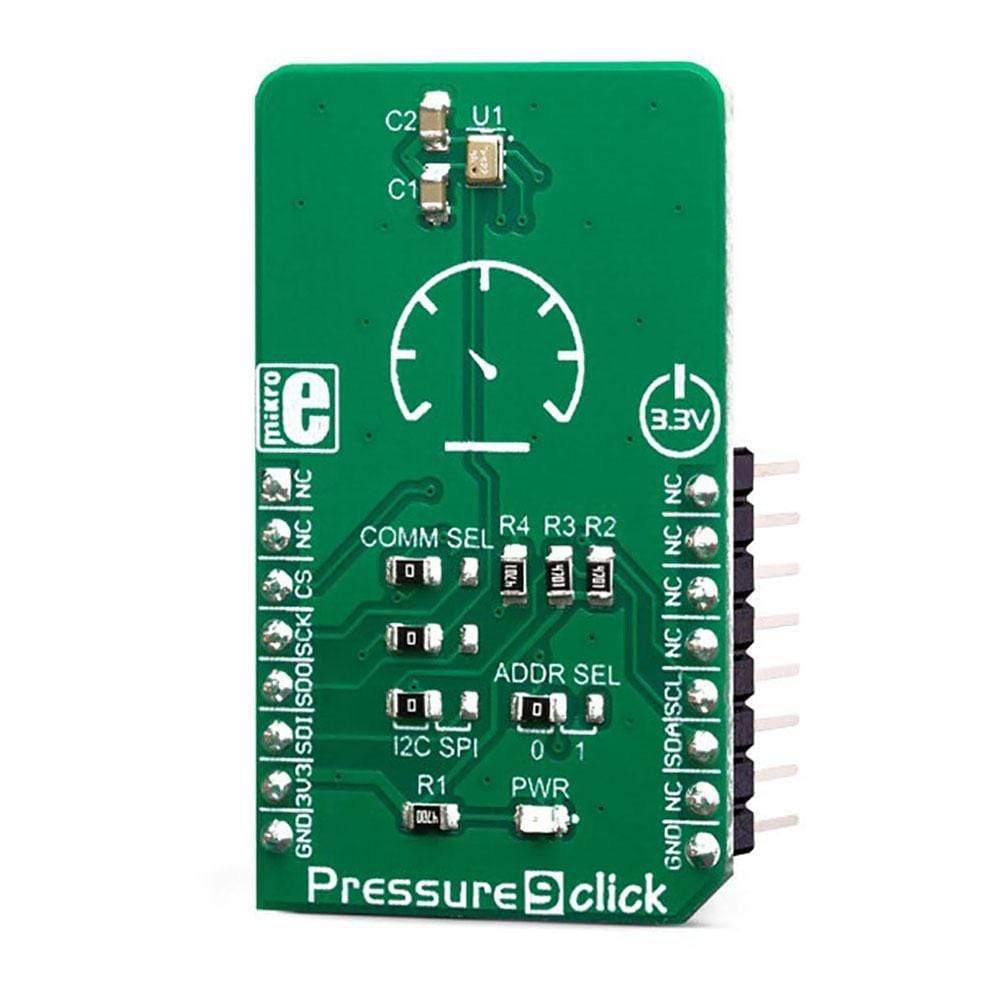
Pressure 9 Click Board™
SKU: MIKROE-3441
Couldn't load pickup availability


Overview
The Pressure 9 Click Board™ is a digital barometric air pressure sensor Click Board™. It is equipped with the DPS422, barometric air pressure sensor, based on a capacitive sensor element. Besides the pressure, this sensor can also measure temperature. Measurement data is available over the I2C or SPI interface, along with the factory-calibrated coefficients, used for high-accuracy data conversion. The device also features 32 words-long FIFO buffer, low power consumption, and very high precision, thanks to an integrated 24-bit A/D converter.
The Pressure 9 Click Board™ can be used within the pressure range from 300 to 1200hPa and temperature in the range from -40⁰C to +85⁰C.
Downloads
The DPS422 is designed with the low-power consumption in mind, has a very small size, and requires a low number of external components. These features make the DPS422 a perfect choice for an IoT or battery-powered application. Therefore, Pressure 9 click can be used as a tool for development of various pressure-based IoT applications, as well as other applications where the power consumption and constrained space could be a problem: portable weather stations, room temperature control, applications related to elevation gain and vertical speed detection, sports-related wearables, and similar.
How Does The Pressure 9 Click Board™ Work?
The Pressure 9 Click Board™ features the DPS422, a digital barometric air pressure sensor, by Infineon. It can be used to measure absolute pressure values from 300 to 1200hPa. The sensor contains a highly accurate capacity-based Micro Electro-Mechanical Sensor (MEMS), along with a high resolution 24-bit sigma-delta A/D converter (ADC). The MEMS also features a set of factory calibration parameters, stored into its OTP memory. They allow high-precision pressure and temperature data conversions to be performed, enabling results in physical units. By adjusting the oversampling ratio, the developer can find a perfect balance between the accuracy, speed (output data rate), and power consumption, in accordance to the application requirements.
MEMS consists a set of tubular vacuum cells, covered by membranes. By applying a pressure, capacitance of the cell is changed proportionally. Several vacuum cells are connected in parallel, allowing for better sensitivity and less noise. The capacitance of the cells is measured and converted to a voltage which is sampled by the internal 24-bit ADC. The result is available over I2C or SPI interface, depending on the position of the COMM SEL jumpers. The conversion formula is then applied to the raw result value, providing pressure and temperature values in human readable format.
The Pressure 9 Click Board™ supports both SPI and I2C communication interfaces, allowing it to be used with a wide range of different MCUs. The communication interface can be chosen by moving SMD jumpers grouped under the COM SEL to an appropriate position (SPI or I2C). The slave I2C address can also be configured by a SMD jumper, when operated in the I2C mode: a SMD jumper labeled as ADD SEL is used to set the least significant bit (LSB) of the I2C address. When set to 0, the 7-bit I2C slave address becomes 0b1110110x. If set to 1, the address becomes 0b1110111x. The last digit (x) is the R/W bit. Please note that each jumper should be moved to the same position, else the communication with the host MCU may not be possible.
One of distinctive features of the DPS422 is the FIFO buffer with 32 slots, allowing to buffer both pressure and temperature readings. The FIFO buffer can be used as a temporary storage for the incoming data, allowing for reduced data traffic through the communication bus. The FIFO buffer can be very useful for writing an optimized MCU firmware. The least significant bit (LSB) of the result stored within the FIFO buffer, determines if the stored data represents pressure, or temperature (1 is used for pressure, 0 for temperature). A bit within the FIFO status register indicates if the buffer is full or if the watermark level has been reached. The FIFO buffer can also be disabled, allowing data to be fetched from the output registers, directly.
Pressure and thermal data are available at the output, in 24-bit, two's complement format. To convert the raw data into a human-readable format, the firmware of the host MCU has to obtain the calibration data. Calibration coefficients are then used within pressure or temperature conversion formulas. The required formulas can be found within the datasheet of the DPS422. However, the Pressure 9 Click Board™ comes with the mikroSDK compatible library of functions that simplify the firmware development. The developer is able to use simple function calls, which perform all the necessary data conversion, returning the pressure and thermal data in human readable format.
The Pressure 9 Click Board™ is designed to be operated by 3.3V logic levels only. A proper logic voltage level translation should be performed before the Click board™ is used MCUs which are operated at 5V.
SPECIFICATIONS
| Type | Pressure |
| Applications | A perfect tool for development of various pressure-based IoT applications, as well as other low-power and space-constrained applications: portable weather stations, room temperature control, applications related to elevation gain and vertical speed detection, sports-related wearables, and similar. |
| On-board modules | DPS422, a digital barometric air pressure sensor, by Infineon. |
| Key Features | 24-bit conversion, high precision, low power consumption, low count of external components required, both pressure and temperature data, factory programmed calibration parameters, perfect for IoT based applications. |
| Interface | I2C,SPI |
| Compatibility | mikroBUS |
| Click board size | M (42.9 x 25.4 mm) |
| Input Voltage | 3.3V |
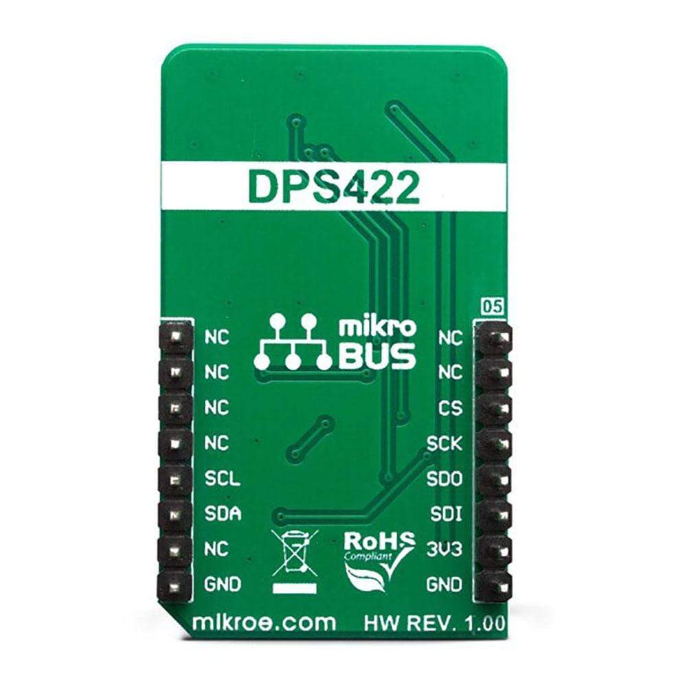
PINOUT DIAGRAM
This table shows how the pinout on the Pressure 9 Click Board™ corresponds to the pinout on the mikroBUS™ socket (the latter shown in the two middle columns).
| Notes | Pin | Pin | Notes | ||||
|---|---|---|---|---|---|---|---|
| NC | 1 | AN | PWM | 16 | NC | ||
| NC | 2 | RST | INT | 15 | NC | ||
| Control IN 2 | CS | 3 | CS | RX | 14 | NC | |
| SPI Clock | SCK | 4 | SCK | TX | 13 | NC | |
| SPI Data OUT | SDO | 5 | MISO | SCL | 12 | SCL | I2C Clock |
| SPI Data IN | SDI | 6 | MOSI | SDA | 11 | SDA | I2C Data |
| Power Supply | 3.3V | 7 | 3.3V | 5V | 10 | NC | |
| Ground | GND | 8 | GND | GND | 9 | GND | Ground |
PRESSURE 9 CLICK ELECTRICAL SPECIFICATIONS
| Description | Min | Typ | Max | Unit |
|---|---|---|---|---|
| Pressure range | 300 | 1200 | hPa | |
| Temperature range | -40 | +85 | ˚C |
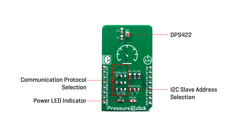
ONBOARD SETTINGS AND INDICATORS
| Label | Name | Default | Description |
|---|---|---|---|
| LD1 | PWR | - | Power LED Indicator |
| JP1, JP3 | COM SEL | Left | Communication interface selection: left position I2C, right position SPI |
| JP4 | ADDR SEL | Left | Slave I2C address LSB selection: left position 0, right position 1 |
| General Information | |
|---|---|
Part Number (SKU) |
MIKROE-3441
|
Manufacturer |
|
| Physical and Mechanical | |
Weight |
0.018 kg
|
| Other | |
EAN |
8606018714889
|
Frequently Asked Questions
Have a Question?
Be the first to ask a question about this.