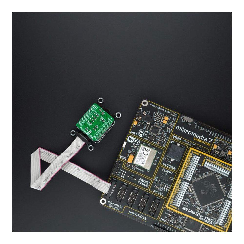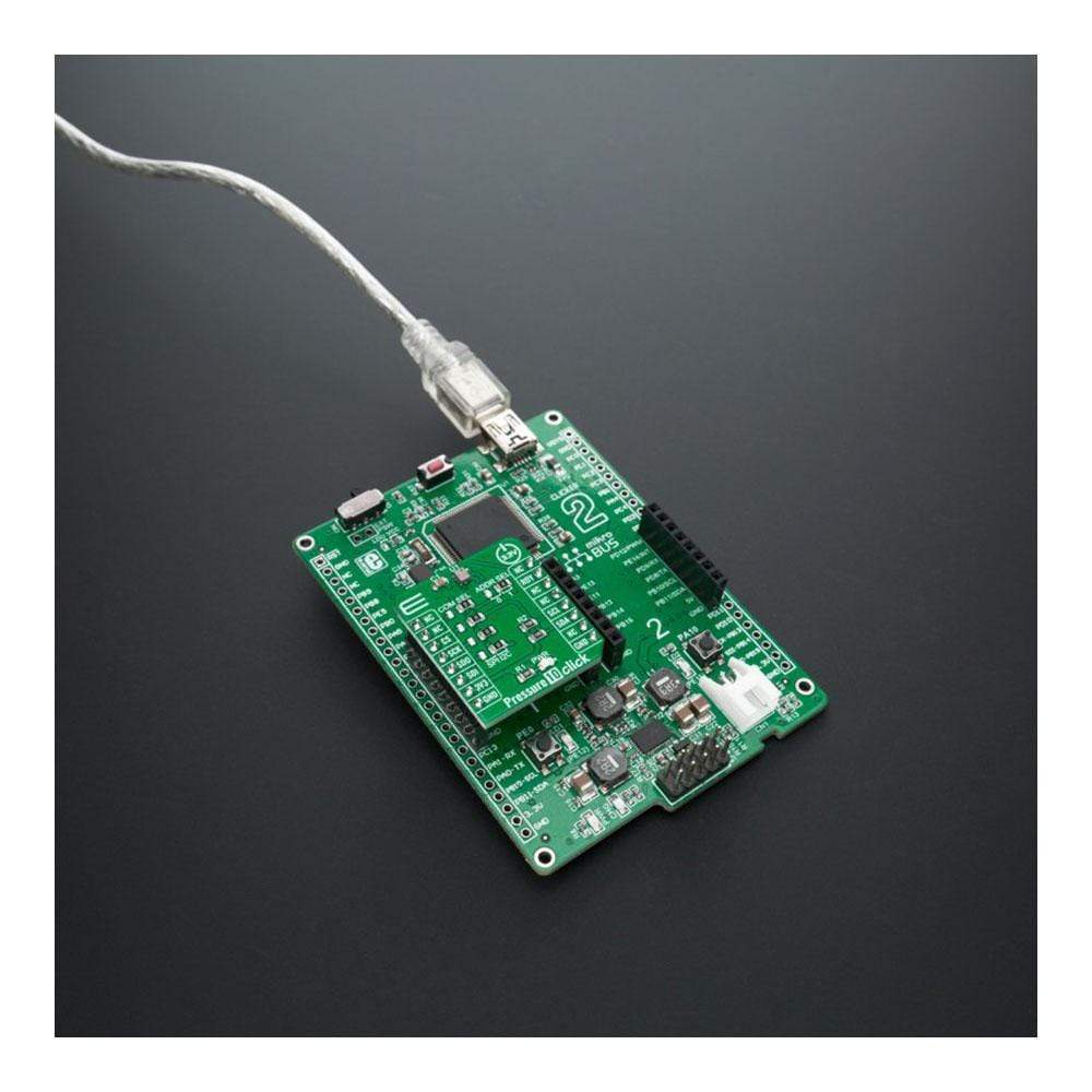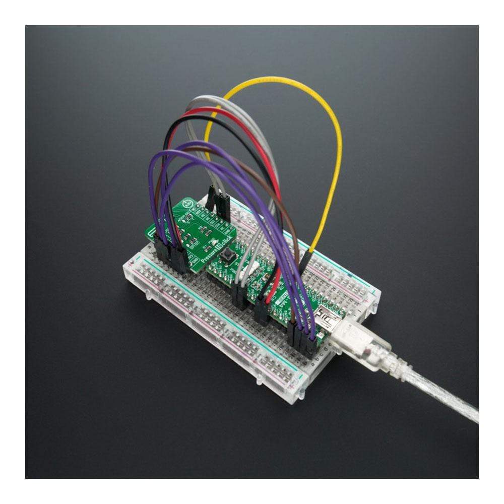
Overview
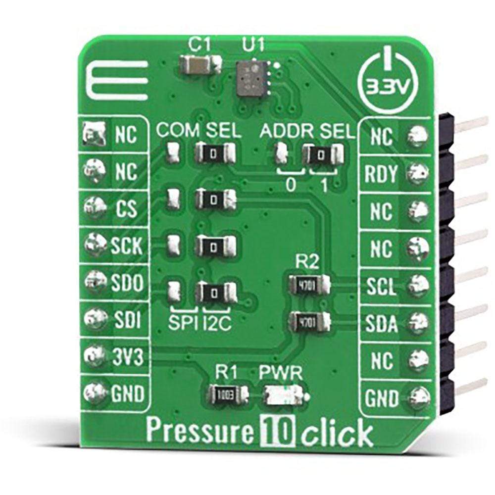
The Pressure 10 Click Board™ features a digital interface barometric pressure sensor, based on the piezoresistive bridge, labelled as HSPPAD042A, from ALPS Electric. It can use both SPI and I2C communication protocols, allowing it to be interfaced with a broad range of MCUs. Besides the pressure readings, this Click Board™ also offers a very accurate temperature reading, which is required for the pressure readings compensation and can be used in a wide range of battery-powered and portable applications thanks to its very low power consumption.
In addition, this product supports averaging and filtering for lower noise, and FIFO function. All these features make the Pressure 10 Click Board™ an ideal solution for the development of portable weather station applications, indoor navigation, altitude control for drones, and similar applications that rely on barometric pressure measurements.
Downloads
How Does The Pressure 10 Click Board™ Work?
The Pressure 10 Click Board™ uses the HSPPAD042A IC, a digital pressure sensor, from ALPS ELECTRIC. This sensor consists of a piezoresistive pressure sensing element and a mixed-signal ASIC which performs A/D conversions and provides the conversion results through a digital interface. MEMS technology, which this sensor element is made of, offers a high sensing precision with ±0.7hPa absolute and ±0.05hPa relative pressure accuracy and industry-lowest current consumption of 1.8μA in low power mode. The sensor is enclosed in a small LGA package and can operate in a range of 300 hPa to 1100 hPa but can withstand up to 30,000 hPa before the membrane breaks down.
The HSPPAD042A offers a set of pressure and temperature measurement options. Several measurement modes can be set by CTL1.MODE bit in 0x0F register:
- Register Action Mode: Allows access to ACTL1 (Action Control) register and execute temperature and pressure measurements by setting TDET and PDET bits to "1". After measurements, the device goes to the standby state and minimizes current consumption waiting for the next command.
- Continuous Measurement Mode: Executes measurement with specified frequency. To move into this mode, PMES bit in CTL2 (Control) register must be set to "1". Measurement is started immediately after measurement mode transition and the following measurement is repeated.
- Command Action Mode: In this mode, several functions are performed by writing "1" at the same bit name in ACTL1 and ACTL2 registers (perform only pressure or temperature measurement, perform a software reset, or perform both pressure and temperature measurement).
After software reset command is detected, the digital regulator is disabled and all register values are reset and measurement mode is set to Register Action Mode. FIFO buffer allows for an optimization of the host firmware, reducing the data traffic through the communication interface. The interrupt is available over the RDY pin (Data Ready pin), and can be used to indicates measurement completion. Multiple flags can be set to the RDY pin. They are all OR output and the change will be effective immediately even during the measurement.
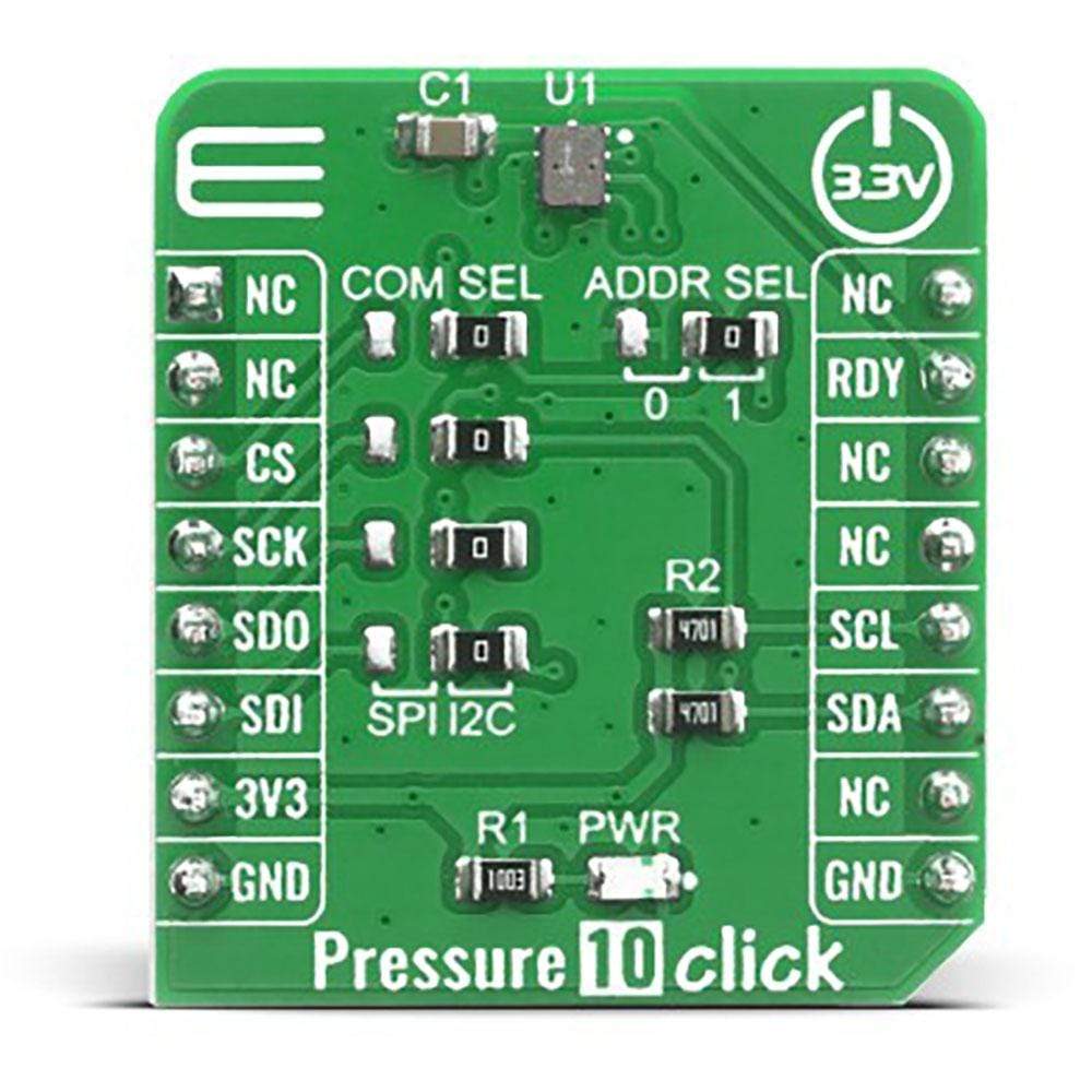
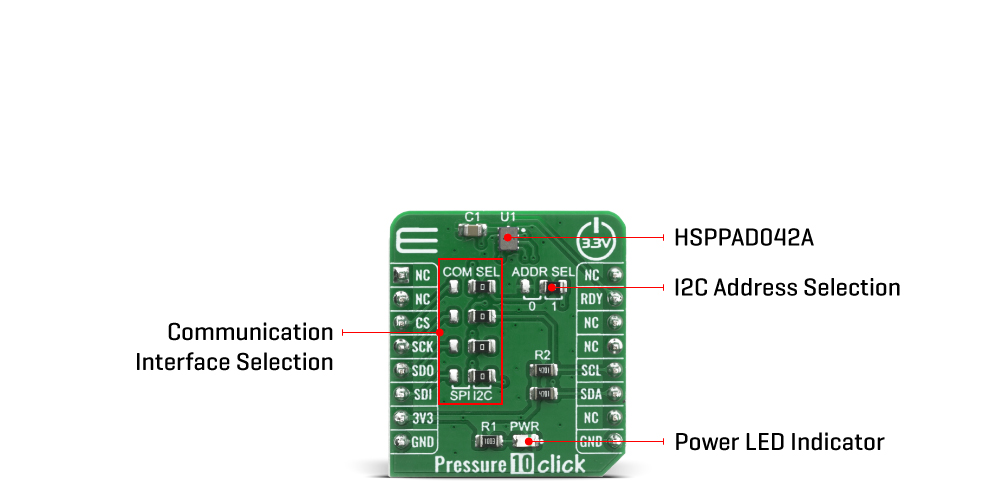
The Pressure 10 Click Board™ offers a choice between two interfaces: I2C and SPI. The selection can be done by positioning SMD jumpers labeled as COMM SEL to an appropriate position. Note that all the jumpers must be placed to the same side, or else the Click board™ may become unresponsive. While the I2C interface is selected, the HSPPAD042A allows the choice of the least significant bit (LSB) of its I2C slave address. This can be done by using the SMD jumper labeled as ADDR SEL.
The Pressure 10 Click Board™ uses both I2C and SPI communication interfaces. It is designed to be operated only with 3.3V logic levels. A proper logic voltage level conversion should be performed before the Click board™ is used with MCUs with logic levels of 5V. More information about the HSPPAD042A can be found in the attached datasheet. However, the Click board™ comes equipped with a library that contains easy to use functions and a usage example that may be used as a reference for the development.
SPECIFICATIONS
| Type | Pressure |
| Applications | An ideal solution for the development of portable weather station applications, indoor navigation, altitude control for drones, and similar applications that rely on barometric pressure measurements. |
| On-board modules | The Pressure 10 Click Board™ uses the HSPPAD042A IC, a digital pressure sensor, from ALPS ELECTRIC. |
| Key Features | Industry-lowest current consumption, 300 hPa to 1100 hPa range, temperature reading, averaging, noise filtering, FIFO function. |
| Interface | GPIO,I2C,SPI |
| Compatibility | mikroBUS |
| Click board size | S (28.6 x 25.4 mm) |
| Input Voltage | 3.3V |
PINOUT DIAGRAM
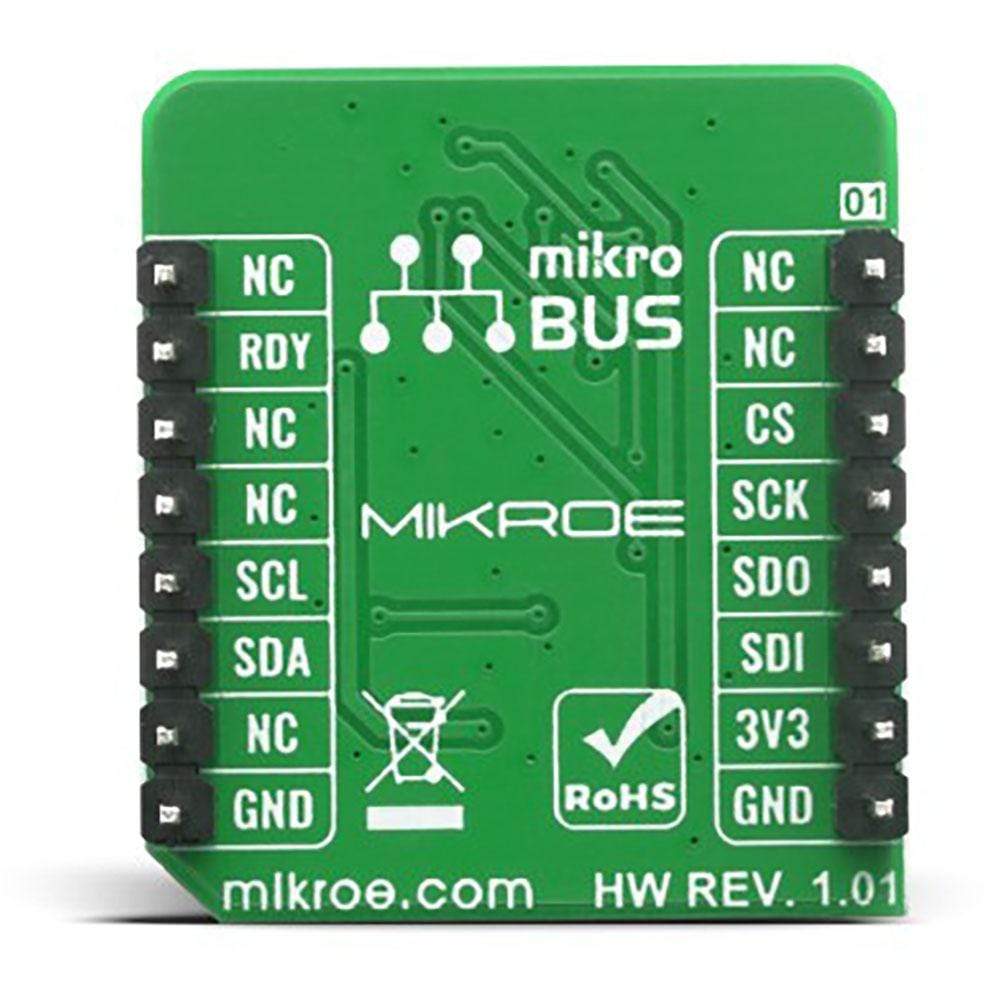
This table shows how the pinout on the Pressure 10 Click Board™ corresponds to the pinout on the mikroBUS™ socket (the latter shown in the two middle columns).
| Notes | Pin |  |
Pin | Notes | |||
|---|---|---|---|---|---|---|---|
| NC | 1 | AN | PWM | 16 | NC | ||
| NC | 2 | RST | INT | 15 | RDY | Data Ready Interrupt | |
| SPI Chip Select | CS | 3 | CS | RX | 14 | NC | |
| SPI Clock | SCK | 4 | SCK | TX | 13 | NC | |
| SPI Data OUT | SDO | 5 | MISO | SCL | 12 | SCL | I2C Clock |
| SPI Data IN | SDI | 6 | MOSI | SDA | 11 | SDA | I2C Data |
| Power Supply | 3.3V | 7 | 3.3V | 5V | 10 | NC | |
| Ground | GND | 8 | GND | GND | 9 | GND | Ground |
ONBOARD SETTINGS AND INDICATORS
| Label | Name | Default | Description |
|---|---|---|---|
| LD1 | PWR | - | Power LED Indicator |
| JP1-JP4 | COM SEL | Right | Communication Interface Selection: Left position SPI, Right position I2C |
| JP5 | ADDR SEL | Right | I2C Address Selection: Left position 0, Right position 1 |
PRESSURE 10 CLICK ELECTRICAL SPECIFICATIONS
| Description | Min | Typ | Max | Unit |
|---|---|---|---|---|
| Supply Voltage | -0.5 | - | 4.0 | V |
| Maximum Load Pressure | - | - | 30000 | hPa |
| Operating Temperature Range | -40 | - | +125 | °C |
| Current consumption (Low power mode) | - | 1.8 | - | μA |
| Pressure absolute accuracy | - | ±0.7 | - | hPa |
| Pressure relative accuracy | - | ±0.05 | - | hPa |
| General Information | |
|---|---|
Part Number (SKU) |
MIKROE-4142
|
Manufacturer |
|
| Physical and Mechanical | |
Weight |
0.016 kg
|
| Other | |
Country of Origin |
|
HS Code Customs Tariff code
|
|
EAN |
8606018717705
|
Warranty |
|
Frequently Asked Questions
Have a Question?
Be the first to ask a question about this.

