


Mikroelektronika d.o.o.
Opto 4 Click Board
Opto 4 Click Board
Couldn't load pickup availability
The Opto 4 Click Board™ is a galvanically isolated power switch, which uses a power MOSFET in combination with an optocoupler. The power MOSFET can withstand significant current due to its low ON resistance, allowing this Click Board™ to be used with different kinds of power demanding applications.
In addition, the Opto 4 Click Board™ is equipped with a voltage limiting circuit, which cuts off the power supply when the voltage of the externally connected power supply suddenly drops. The galvanic isolation of the optocoupler offers protection of the controller circuit, thus preventing power surges from the controlled circuit.
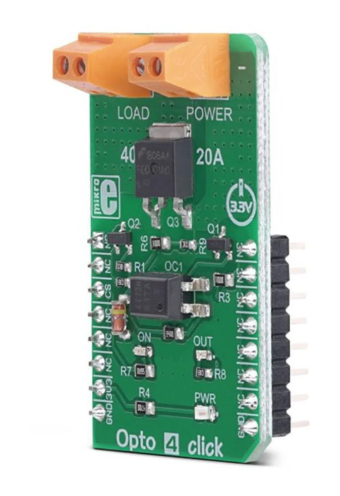
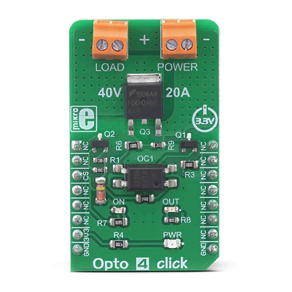

Featuring very good electrical specifications, including high operating voltage, high current capacity, optical galvanic isolation of the controller circuit, and under-voltage protection, the Opto 4 Click Board™ is a perfect solution that can be used for the development of a wide range of power demanding applications, including driving of LED stripes, light bulbs, different types of DC motors, and other similar applications that require an electronically controlled high-current switch.
How Does The Opto 4 Click Board™ Work?
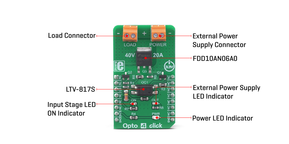
The Opto 4 Click Board™ uses the LTV-817S, an optocoupler with a high isolation voltage, by LITEON. This is a single-channel optocoupler that uses the low current provided by the output pin of the microcontroller (MCU) to activate its output stage. Besides an internal biasing LED, the MCU drives an additional external yellow LED, which signalizes that the MCU output is at a HIGH logic level. This led is labelled as ON, and it is used to indicate the state of the optocoupler output stage (conductive or non-conductive). The host MCU uses the CS pin of the mikroBUS™ to drive the input stage of the LTV-817S optocoupler.
The working principle of an optocoupler is quite simple: A photo-emitting element - usually an IR LED - is integrated on a die along with the photosensitive element, usually a photosensitive transistor. The LED and the photosensitive transistor are isolated galvanically, but not optically: when the internal LED is powered, it emits light, which biases the base of the photosensitive transistor at the output stage, allowing the current to flow through it. In practice, an optocoupler may be equipped with additional elements such as Schmitt triggers, photo-sensitive Darlington pairs, various configurations of MOSFETs, etc.
The output stage of the optocoupler is used to drive the gate terminal of the FDD10AN06A0, an external power MOSFET, manufactured using the PowerTrench® technology, by ON Semiconductor. This MOSFET allows much more current to flow through the connected load, due to its extremely low ON resistance of about 10 mΩ, typically (10V). This MOSFET is designed to be used in switching circuits and for DC/DC converters, providing high efficiency for these applications. As such, it has a very low capacitance on its gate terminal, allowing it to be driven with reasonably high-frequency PWM signals.
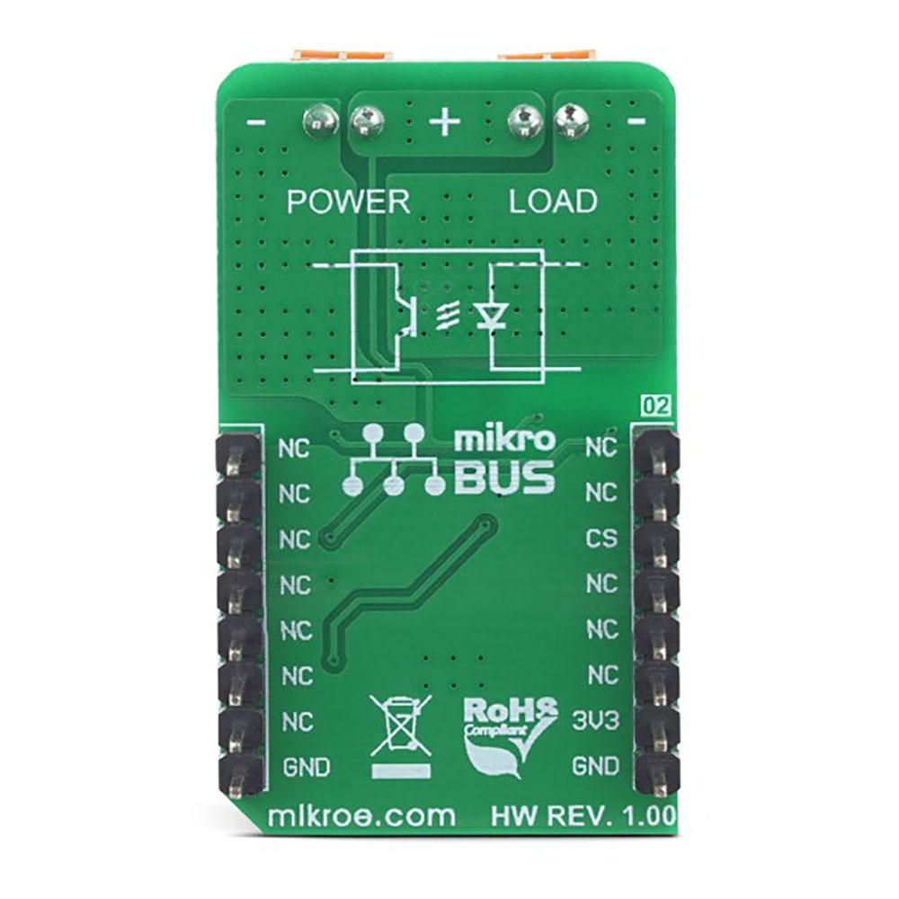
The output stage of the LTV-817S optocoupler is connected to the VIN terminal of the external power supply connector, labelled as POWER. When the output stage of the optocoupler is closed (CS pin of the mikroBUS™ is at a HIGH logic level), it will connect the gate of the power MOSFET to the VIN voltage, thus enabling the power MOSFET. When the output stage of the optocoupler is opened (CS pin is at a LOW logic level), the gate of the MOSFET will be pulled down to the GND, by a 10K resistor, disabling the MOSFET. While enabled, the power MOSFET will be able to conduct the current through an external load, connected to the LOAD terminal. The output stage of the optocoupler also has a green LED indicator labelled as OUT, which indicates that there is a valid voltage level across the POWER terminal.
An Undervoltage circuit on the VIN terminal prevents the voltage of the external power supply to drop under 10V. Ideally, the power supply voltage should stay above 12V. It is important for the voltage of the power supply to stay above 10V, since in that case, the ON resistance of the MOSFET is about 10 mΩ, ensuring that no significant heat dissipation will occur as a result of high current through the load. As the voltage of the externally connected power supply drops, it may cause the ON resistance of the power MOSFET to rise enough even before activating the Undervoltage circuit (depending on the current through the load), resulting in its damage. Therefore, the voltage of the external power supply must stay above 10V for this Click board™ to work reliably.
The under-voltage protection feature can be useful to switch off the load in the case when the short-circuit condition occurs: the voltage of the power supply during the short circuit event may drop, resulting in the Undervoltage circuit being activated. However, if a reasonably strong power supply is used, the short-circuit current may be enough to destroy the power MOSFET or the input terminals.
SPECIFICATIONS
| Type | Optocoupler |
| Applications | The Opto 4 Click Board™ is a perfect solution for the development of a wide range of power demanding applications, including driving of LED stripes, light bulbs, different types of DC motors, and other similar applications that require an electronically controlled high-current switch. |
| On-board modules | LTV-817S, a high isolation voltage optocoupler by LITEON; FDD10AN06A0, an external power MOSFET, manufactured using the PowerTrench® technology, by ON Semiconductor. |
| Key Features | Excellent ON resistance of only 10 mΩ, high current conduction capability, high maximum voltage, an under-voltage circuit that ensures the ON resistance of the MOSFET stays within the specified values, etc. |
| Interface | GPIO |
| Compatibility | mikroBUS |
| Click board size | M (42.9 x 25.4 mm) |
| Input Voltage | 3.3V |
PINOUT DIAGRAM
This table shows how the pinout on the Opto 4 Click Board™ corresponds to the pinout on the mikroBUS™ socket (the latter shown in the two middle columns).
| Notes | Pin | Pin | Notes | ||||
|---|---|---|---|---|---|---|---|
| NC | 1 | AN | PWM | 16 | NC | ||
| NC | 2 | RST | INT | 15 | NC | ||
| Optocoupler IN | CS | 3 | CS | RX | 14 | NC | |
| NC | 4 | SCK | TX | 13 | NC | ||
| NC | 5 | MISO | SCL | 12 | NC | ||
| NC | 6 | MOSI | SDA | 11 | NC | ||
| Power Supply | +3V3 | 7 | 3.3V | 5V | 10 | NC | |
| Ground | GND | 8 | GND | GND | 9 | GND | Ground |
ONBOARD SETTINGS AND INDICATORS
| Label | Name | Default | Description |
|---|---|---|---|
| LD1 | PWR | - | Power LED indicator |
| LD2 | ON | - | Input stage ON LED indicator |
| LD3 | OUT | - | External power supply LED indicator |
Software Support
We provide a library for the Opto 4 Click Board™ on our LibStock page, as well as a demo application (example), developed using MikroElektronika compilers. The demo can run on all the main MikroElektronika development boards.
Library Description
The library contains a function for enabling or disabling the output voltage.
Key Functions
void opto4_outputEnable(uint8_t enable)- Function for output enable or disable.
Example Description
The application is composed of three sections :
- System Initialization - Sets CS pin as OUTPUT.
- Application Initialization - Initialization driver init.
- Application Task - (code snippet) - The Output voltage enabled and disabled every 3 sec.
void applicationTask()
{
    opto4_outputEnable(_OPTO4_OUTPUT_ENABLE);
    Delay_ms( 3000 );
    opto4_outputEnable(_OPTO4_OUTPUT_DISABLE);
    Delay_ms( 3000 );
}
The full application code, and ready to use projects can be found on our LibStock page.
Other mikroE Libraries used in the example:
GPIO
Additional Notes and Information
Depending on the development board you are using, you may need a USB UART click, USB UART 2 click or RS232 click to connect to your PC, for development systems with no UART to USB interface available on the board. The terminal available in all MikroElektronika compilers, or any other terminal application of your choice, can be used to read the message.
Opto 4 Click Board
Frequently Asked Questions
Have a Question?
Be the first to ask a question about this.