


Mikroelektronika d.o.o.
Temp-Log 7 Click Board™
Temp-Log 7 Click Board™
SKU: MIKROE-5598
Couldn't load pickup availability
Key Features
Overview
Introducing the Temp-Log 7 Click Board™: Ultimate Solution for Accurate Temperature Measurement
Discover the Temp-Log 7 Click Board™, a powerful and compact add-on board designed to measure precisely and record temperature fluctuations in your environment. Equipped with the state-of-the-art TMP1826 temperature sensor from Texas Instruments, this board offers high accuracy and reliability. It is perfect for industrial, consumer, and environmental applications where exact temperature measurement is crucial.
Key Features of the Temp-Log 7 Click Board™
With an impressive operating temperature range of -20°C to +85°C, the Temp-Log 7 Click Board™ provides ±0.1°C (typical) and ±0.3°C (maximum) accuracy, ensuring precise temperature monitoring. The integrated 2-Kbit EEPROM and factory-programmed 64-bit unique identification number ensure effortless addressing and NIST traceability. Enjoy the convenience of a programmable alarm function, which signals the MCU in the event of a specific temperature event, and the versatility of three configurable digital I/O pins for general purposes or identifying the device's position on a shared bus.
Seamless Software Development with mikroSDK Compliant Library
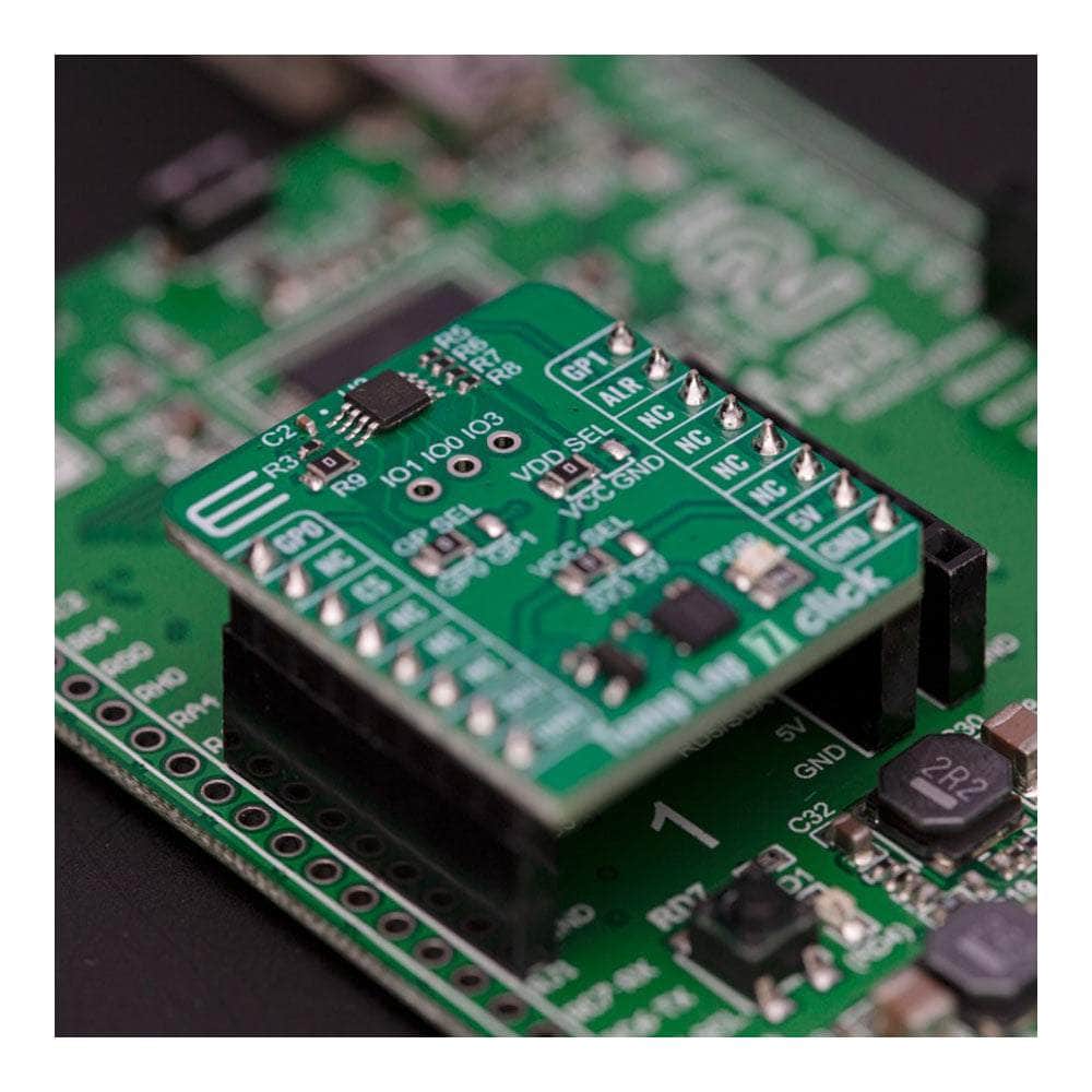
Experience hassle-free software development with the mikroSDK-compliant library, which includes user-friendly functions that simplify the entire process. The Temp-Log 7 Click Board™ is a fully tested product, ready to be integrated into any system equipped with a mikroBUS™ socket.
Upgrade Your Thermal Management Today with the Temp-Log 7 Click Board™
Don't compromise on the accuracy and reliability of your temperature measurements. Choose the Temp-Log 7 Click Board™ for an unparalleled temperature monitoring experience, ensuring the optimal performance of your applications. Get your hands on this advanced and versatile solution today!
Downloads
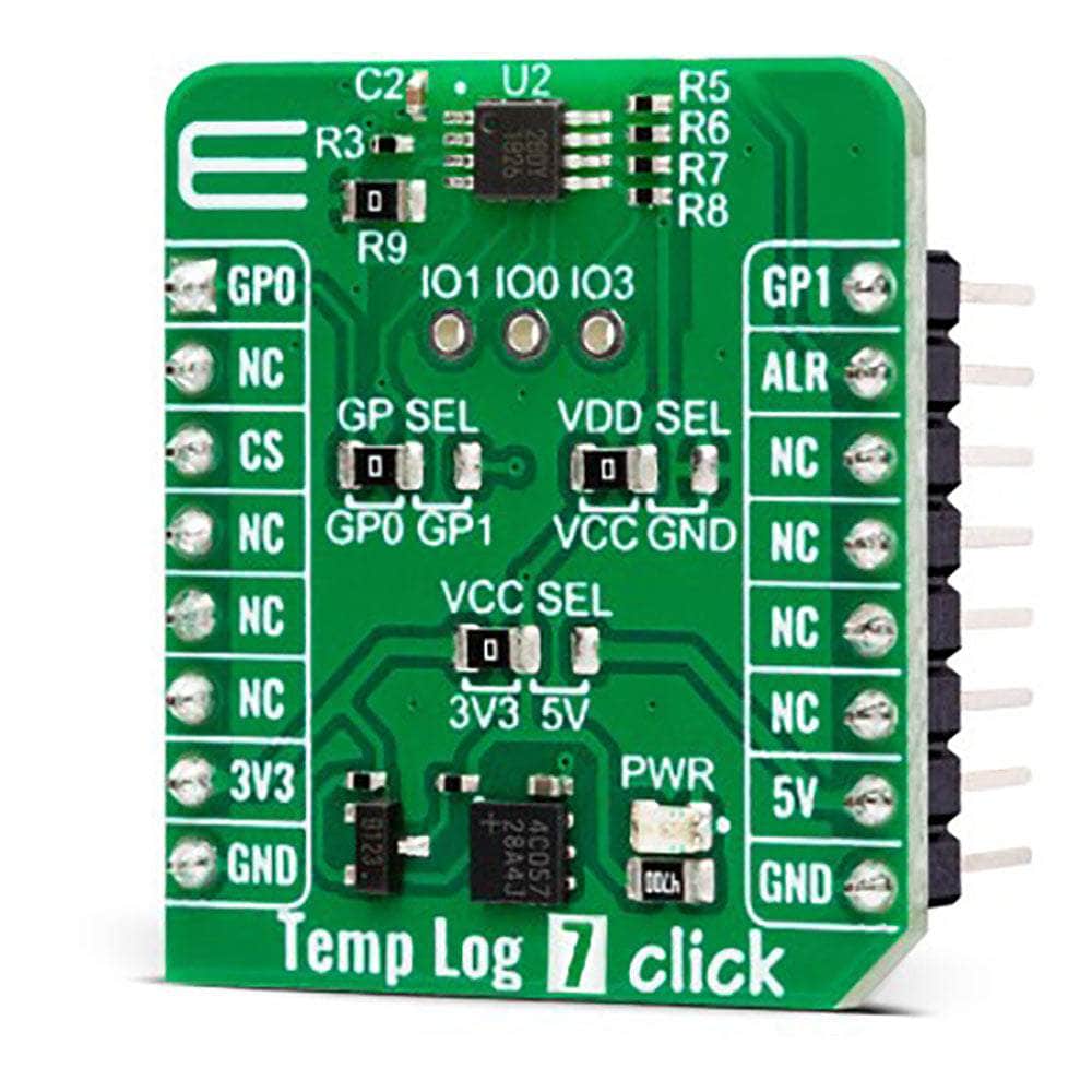
How Does The Temp-Log 7 Click Board™ Work?
The Temp-Log 7 Click Board™ is based on the TMP1826, a digital output temperature sensor from Texas Instruments designed for thermal management and protection applications. The TMP1826 features an integrated 2-kbit user EEPROM that allows the host to store application data in increments of 64 bits. With a user-programmable 256-bit page size write protection to avoid accidental overwrite, the EEPROM can be used as non-volatile, read-only memory. The TMP1826 also features an integrated CRC that may be used for ensuring data integrity during communication. It consists of an internal thermal BJT (NIST traceable factory-programmed non-erasable), a high-resolution analog-to-digital converter (ADC), and a data processing circuit in one package. The voltage is digitized and converted to a 16-bit temperature result in degrees Celsius, giving a digital output with outstanding accuracy of up to ±0.1°C (typical)/±0.3°C (maximum) and temperature resolution of 7.8125m°C, typical over a temperature range of –20°C to +85°C.
This Click board™ communicates with MCU using the 1-Wire interface that, by definition, requires only one data line (and ground) for communication with MCU. The 1-Wire communication line is routed to the SMD jumper labelled GP SEL, which allows routing of the 1-Wire communication either to the GP0 pin or the GP1 pin of the mikroBUS™ socket. These pins are labelled, respectively, the same as the SMD jumper positions, making the selection of the desired pin simple and straightforward. The TMP1826 can operate as a 1-Wire half-duplex bus in supply or bus-powered mode. Selection is made by positioning the SMD jumper marked VDD SEL to the appropriate position labelled VCC or GND. With the jumper set on the VCC position, the TMP1826 is powered by the same supply as this Click board™ or bus powered with the jumper set on the GND position where the device is supplied parasitically from the 1-Wire bus.
Also, the TMP1826 can be configured to operate in various one-shot temperature-conversion modes, such as basic one-shot, auto, and stacked conversion modes. Each conversion mode has a single temperature sample, but the host can enable 8 sample averages in the device for improved accuracy. Depending on the user application case, the TMP1826 also provides user and application configurable address modes. These modes exist alongside the standard device address and are useful for applications requiring faster access and device position identification. One of the ways of setting the address is through the R9 resistor, which, depending on the value of the resistor, provides the possibility of using one of 16 addresses.
The TMP1826 also includes advanced features like a programmable alarm function and three digital I/O pins on an unpopulated header, configurable for general purposes or to identify the device's position on a shared bus. An alarm (interrupt) signal, routed to the ALR pin of the mikroBUS™ socket, is alarming when a specific temperature event occurs that depends on the value of the temperature reading relative to programmable limits.
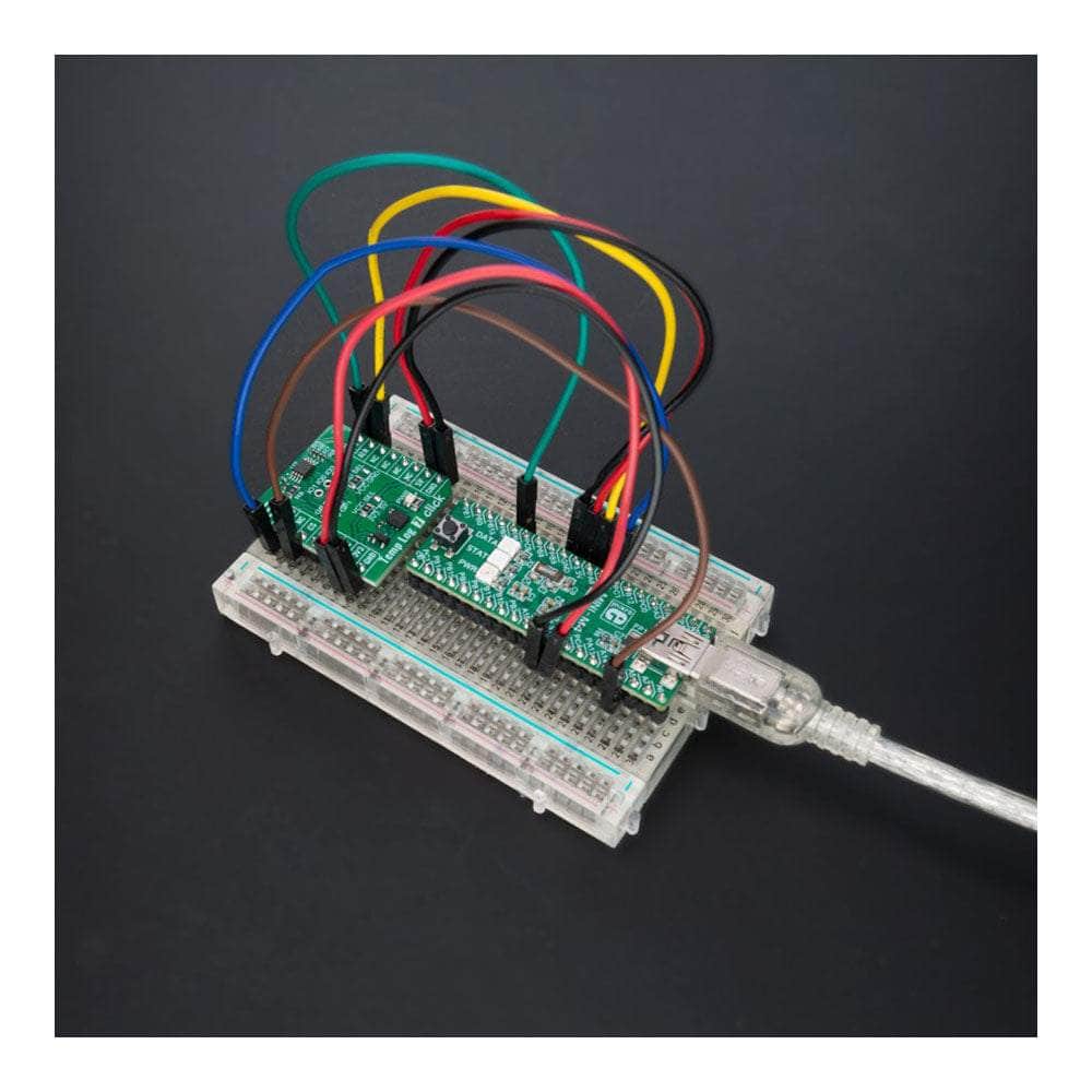
The Temp-Log 7 Click Board™ can operate with either 3.3V or 5V logic voltage levels selected via the VCC SEL jumper. This way, both 3.3V and 5V capable MCUs can use the communication lines properly. However, the Click board™ comes equipped with a library containing easy-to-use functions and an example code that can be used, as a reference, for further development.
SPECIFICATIONS
| Type | Temperature & humidity,Temperature Logging |
| Applications | Can be used for the thermal management of industrial, consumer, and environmental applications |
| On-board modules | TMP1826 - 1-Wire compatible digital output temperature sensor from Texas Instruments |
| Key Features | High accuracy, broad temperature range, 16-bit temperature resolution, flexible user programmable address modes, 2kbit EEPROM, NIST traceable factory-programmed non erasable 64-bit identification number for device addressing, alert, user configurable I/Os, and more |
| Interface | 1-Wire |
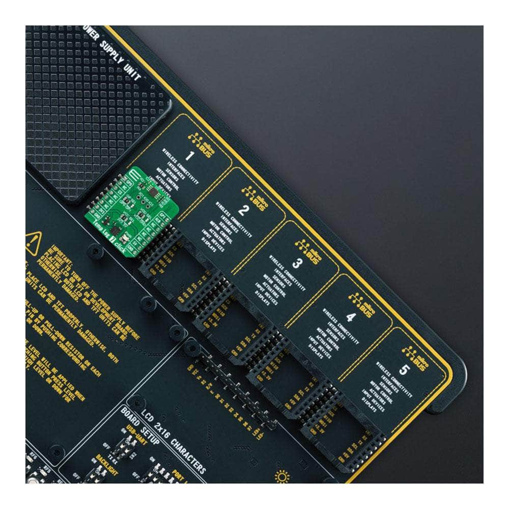
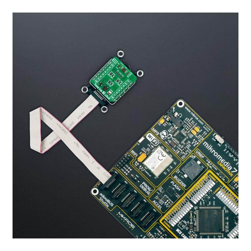
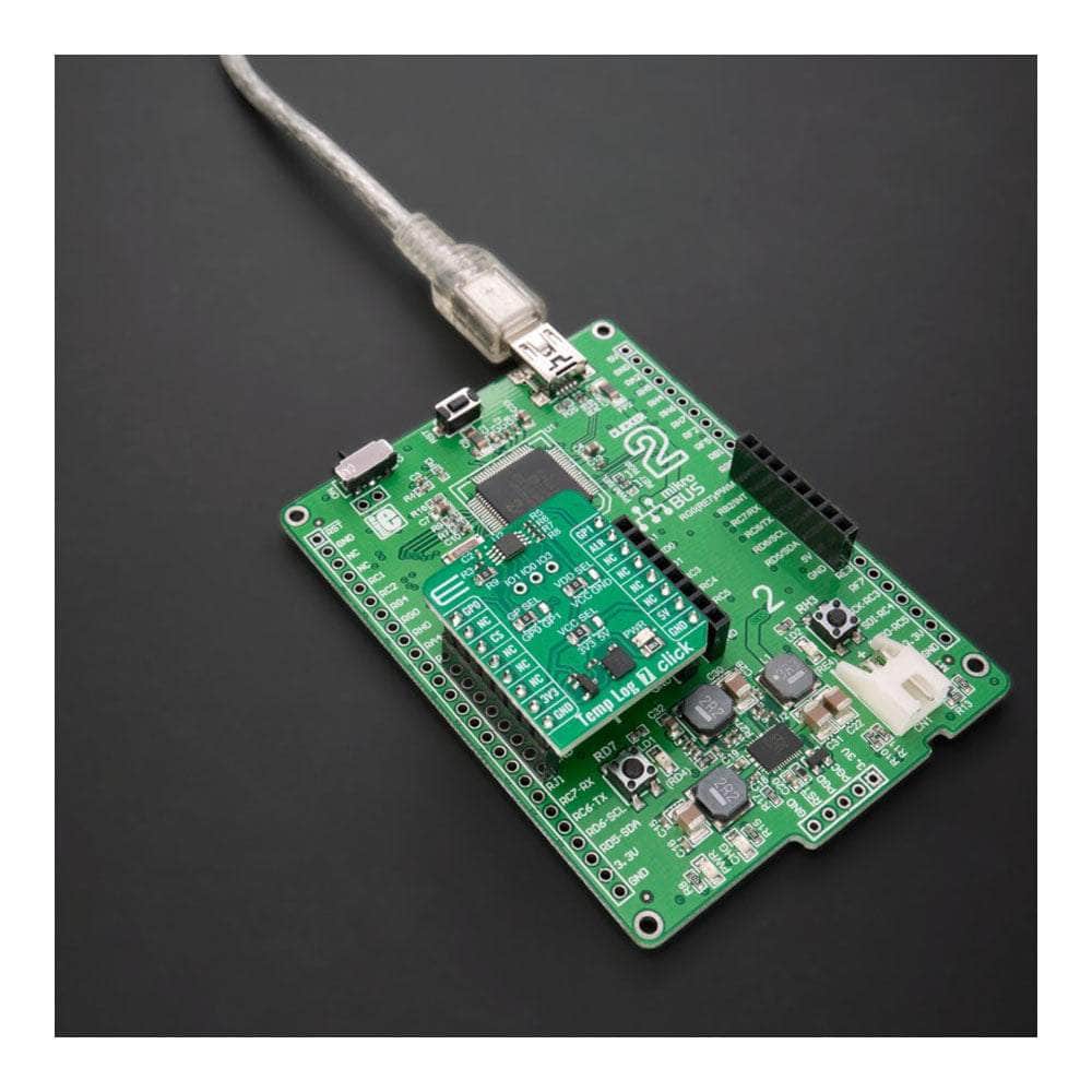
| Compatibility | mikroBUS |
| Click board size | S (28.6 x 25.4 mm) |
| Input Voltage | 3.3V or 5V |
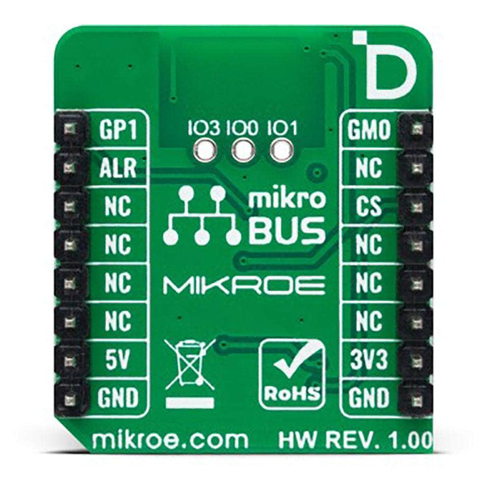
PINOUT DIAGRAM
This table shows how the pinout of the Temp-Log 7 Click Board™ corresponds to the pinout on the mikroBUS™ socket (the latter shown in the two middle columns).
| Notes | Pin | Pin | Notes | ||||
|---|---|---|---|---|---|---|---|
| 1-Wire Data IN/OUT | GP0 | 1 | AN | PWM | 16 | GP1 | 1-Wire Data IN/OUT |
| NC | 2 | RST | INT | 15 | ALT | Alert | |
| NC | 3 | CS | RX | 14 | NC | ||
| NC | 4 | SCK | TX | 13 | NC | ||
| NC | 5 | MISO | SCL | 12 | NC | ||
| NC | 6 | MOSI | SDA | 11 | NC | ||
| Power Supply | 3.3V | 7 | 3.3V | 5V | 10 | 5V | Power Supply |
| Ground | GND | 8 | GND | GND | 9 | GND | Ground |
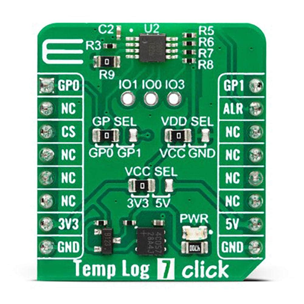
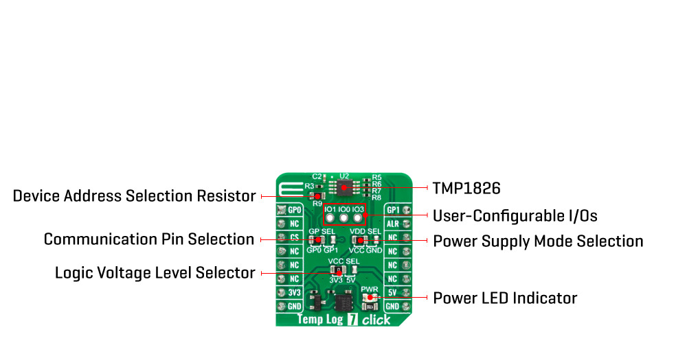
ONBOARD SETTINGS AND INDICATORS
| Label | Name | Default | Description |
|---|---|---|---|
| LD1 | PWR | - | Power LED Indicator |
| JP1 | GP SEL | Left | Communication Pin Selection GP0/GP1: Left position GP0, Right position GP1 |
| JP2 | VDD SEL | Left | Power Supply Mode Selection VCC/GND: Left position VCC, Right position GND |
| JP3 | VCC SEL | Left | Logic Level Voltage Selection 3V3/5V: Left position 3V3, Right position 5V |
| J1 | IO | Unpopulated | User-Configurable I/O Pins Header |
| R9 | R9 | Populated | Device Address Selection Resistor |
TEMP-LOG 7 CLICK ELECTRICAL SPECIFICATIONS
| Description | Min | Typ | Max | Unit |
|---|---|---|---|---|
| Supply Voltage | 3.3 | - | 5 | V |
| Operating Temperature Range | -20 | - | 85 | °C |
| Temperature Accuracy | - | ±0.1 | ±0.3 | °C |
| Temperature Resolution | - | 16 | - | bit |
| - | 7.8125 | - | m°C |
| General Information | |
|---|---|
Part Number (SKU) |
MIKROE-5598
|
Manufacturer |
|
| Physical and Mechanical | |
Weight |
0.02 kg
|
| Other | |
EAN |
8606027384912
|
Frequently Asked Questions
Have a Question?
-
Is the Temp-Log 7 Click Board™ ready to use?
Yes, the Temp-Log 7 Click Board™ comes as a fully tested product, ready to be used on a system equipped with the mikroBUS™ socket.
-
Is there software available for the Temp-Log 7 Click Board™?
Yes, the Temp-Log 7 Click Board™ is supported by a mikroSDK compliant library, which includes functions that simplify software development.
-
What applications is the Temp-Log 7 Click Board™ suitable for?
The Temp-Log 7 Click Board™ is suitable for the thermal management of industrial, consumer, and environmental applications where accurate temperature measurement is critical for proper operation.
-
What are the digital I/O pins on the Temp-Log 7 Click Board™ used for?
The Temp-Log 7 Click Board™ has three digital I/O pins configurable for general purposes or to identify the device's position on a shared bus.
-
What is the programmable alarm function on the Temp-Log 7 Click Board™?
The Temp-Log 7 Click Board™ has a programmable alarm function that outputs an interrupt signal to the MCU when a specific temperature event occurs.
-
What is the unique identification number for addressing on the Temp-Log 7 Click Board™?
The Temp-Log 7 Click Board™ comes with a factory-programmed 64-bit unique identification number for addressing and NIST traceability.
-
What is the accuracy of the Temp-Log 7 Click Board™?
The Temp-Log 7 Click Board™ has a high accuracy of ±0.1°C (typical)/±0.3°C (maximum).
-
What is the operating temperature range of the Temp-Log 7 Click Board™?
The Temp-Log 7 Click Board™ supports a wide operating temperature range from –20°C to +85°C.
-
What sensor does the Temp-Log 7 Click Board™ use?
The Temp-Log 7 Click Board™ features the TMP1826, a high-accuracy, 1-Wire® compatible digital output temperature sensor from Texas Instruments with integrated 2-kbit EEPROM.
-
What is the Temp-Log 7 Click Board™?
The Temp-Log 7 Click Board™ is a compact add-on board used to measure and record the temperature of an environment over time.