


Mikroelektronika d.o.o.
DIGI POT 11 Click Board
DIGI POT 11 Click Board
Couldn't load pickup availability
Key Features:
- Double dual potentiometers, 256-tap linear taper positions, single 3.3V supply, low power consumption, 50kΩ end-to-end resistance, I2C interface, Power-On sets wiper to midscale, and more
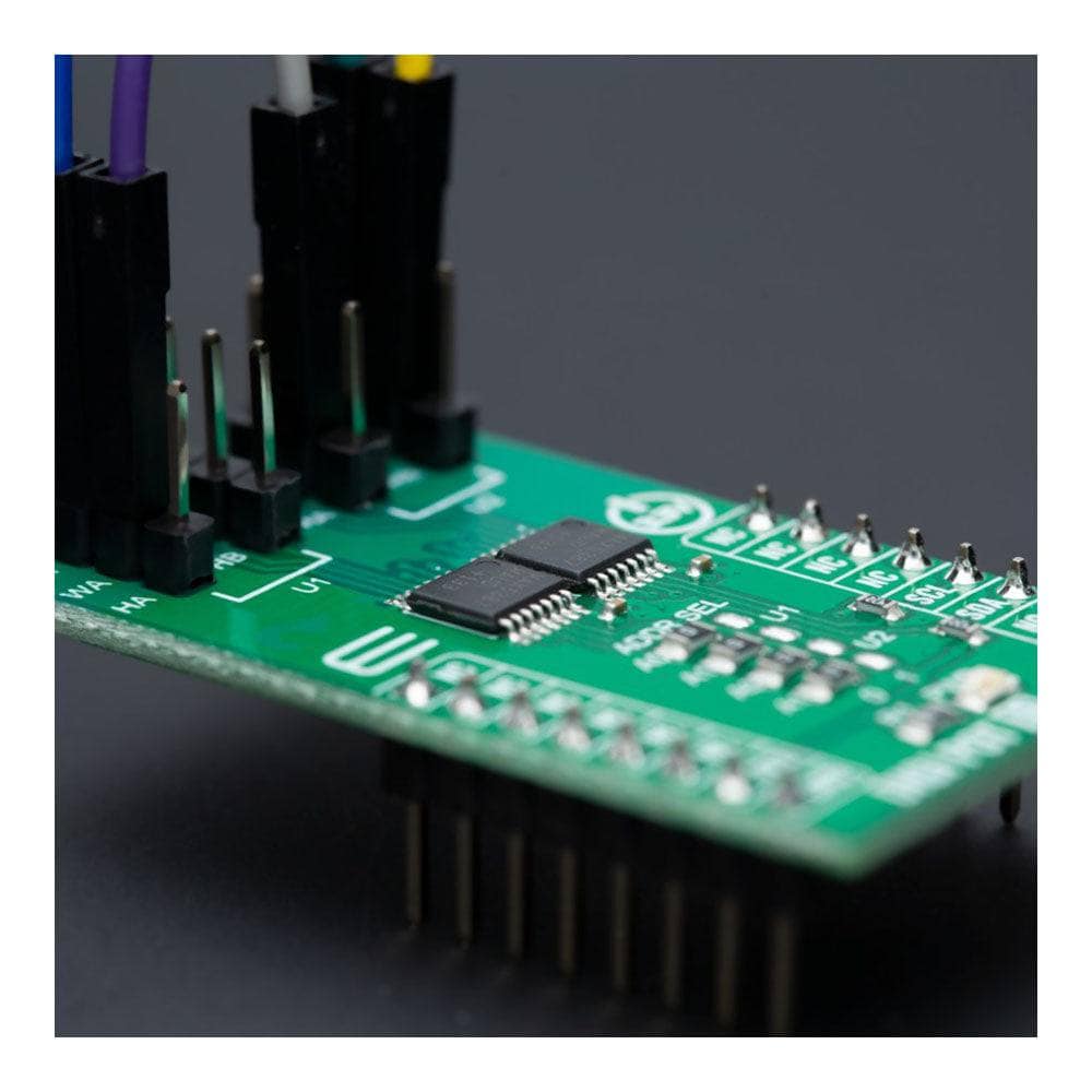
- Based on the MAX5387 - dual volatile linear taper digital potentiometer from Analog Devices
- Can be used as a mechanical potentiometer replacement for the portable consumer market and battery-backup industrial applications
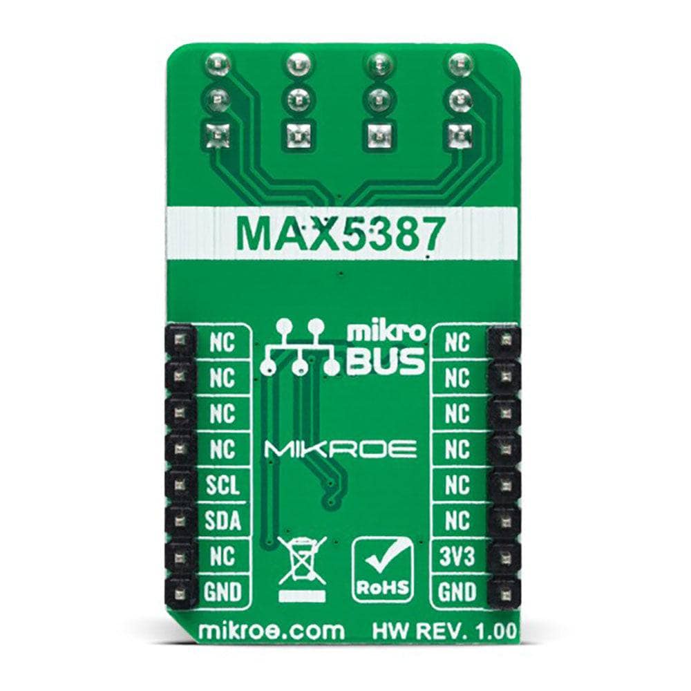
- mikroBUS: I2C Interface
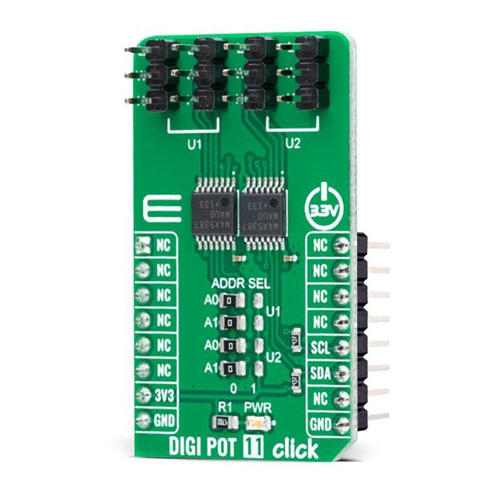
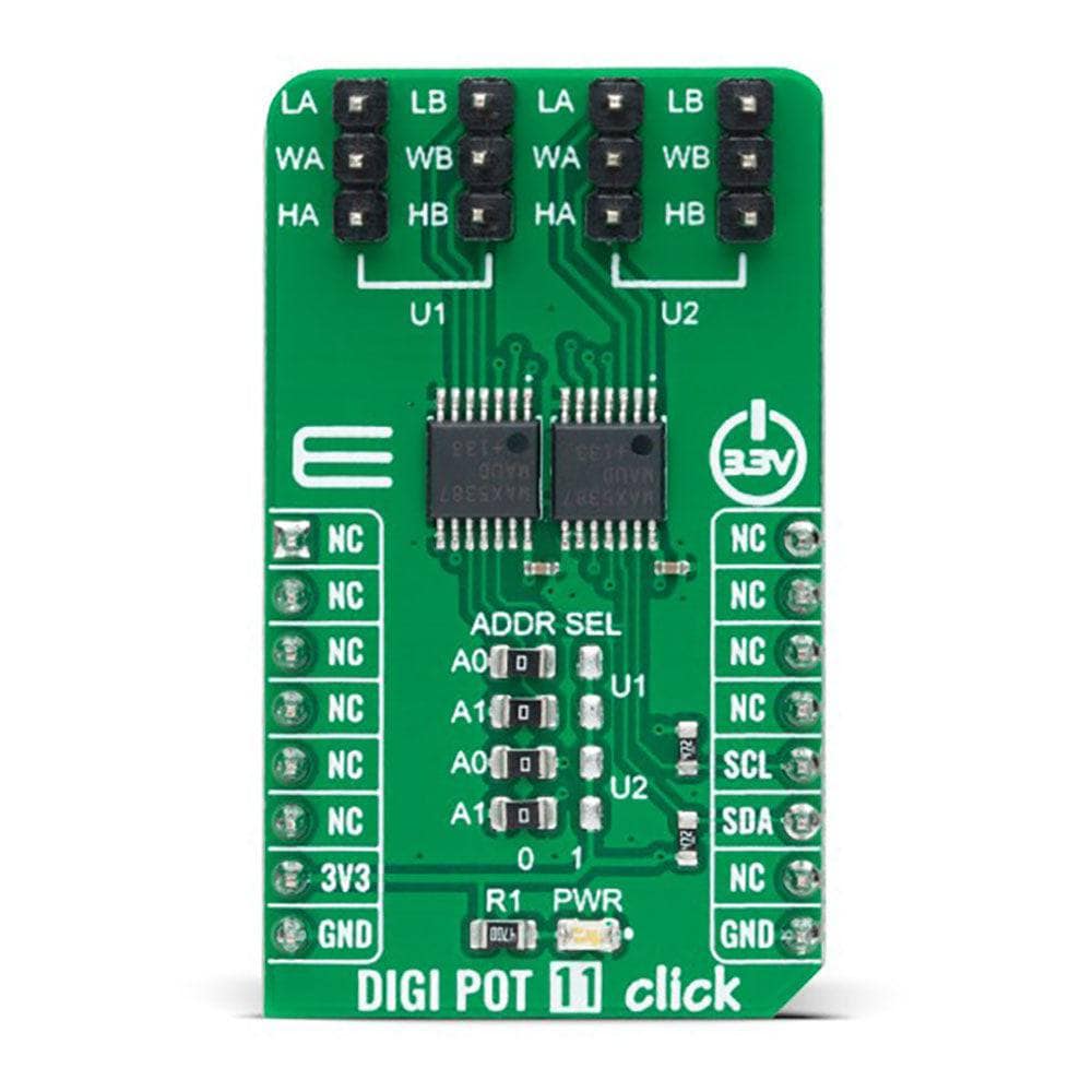
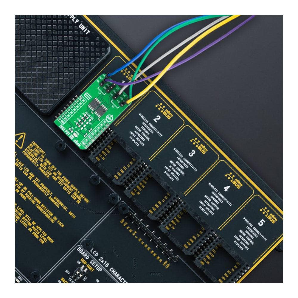
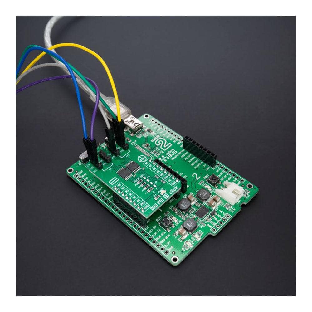
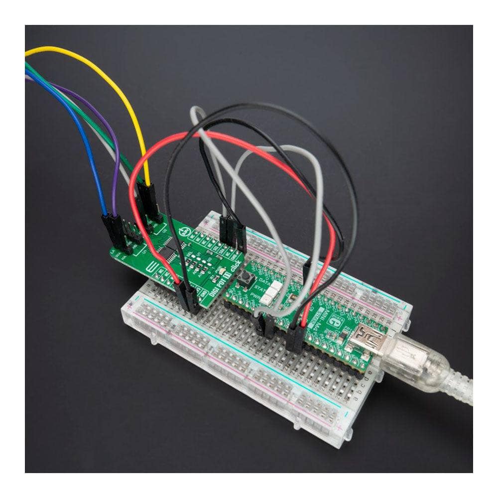
The DIGI POT 11 Click Board™ is a compact add-on board representing a digitally controlled potentiometer. This board features a double pack of the MAX5387, a dual, 256-tap, volatile, low-voltage linear taper digital potentiometer from Analog Devices. This way, four digitally I2C-controlled potentiometers are realized with end-to-end resistance values of 50kΩ. Operating from a single +3.3V power supply, this device provides a low 35ppm/ºC end-to-end temperature coefficient. This Click board™ can be used as a mechanical potentiometer replacement for the portable consumer market and battery-backup industrial applications.
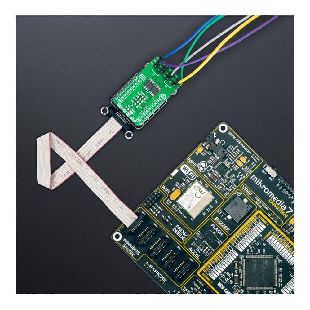
The DIGI POT 11 Click Board™ is supported by a mikroSDK-compliant library, which includes functions that simplify software development. This Click board™ comes as a thoroughly tested product, ready to be used on a system equipped with the mikroBUS™ socket.
Software Support
We provide a library for the DIGI POT 11 Click Board™ as well as a demo application (example), developed using MikroElektronika compilers. The demo can run on all the main MikroElektronika development boards.
The package can be downloaded/installed directly from NECTO Studio The package Manager (recommended), downloaded from our LibStock™ or found on the MikroE Github account.
Library Description
This library contains API for the DIGI POT 11 Click Board™ driver.
Key functions
-
digipot11_set_u1_wiperThis function sets the position of the selected wiper of U1 device by using an I2C serial interface. -
digipot11_set_u2_wiperThis function sets the position of the selected wiper of U2 device by using an I2C serial interface.
Example Description
This example demonstrates the use of the DIGI POT 11 Click Board™ by changing the wipers position of both U1 and U2 devices.
void application_task ( void )
 {
     for ( uint16_t wiper_pos = DIGIPOT11_WIPER_ZERO_SCALE; wiper_pos <= DIGIPOT11_WIPER_FULL_SCALE; wiper_pos += 5 )
     {
         if ( DIGIPOT11_OK == digipot11_set_u1_wiper ( &digipot11, DIGIPOT11_WIPER_SEL_BOTH, ( uint8_t ) wiper_pos ) )
         {
             log_printf( &logger, " U1 wipers position: %urn", wiper_pos );
         }
         if ( DIGIPOT11_OK == digipot11_set_u2_wiper ( &digipot11, DIGIPOT11_WIPER_SEL_BOTH,
                                                       ( uint8_t ) ( DIGIPOT11_WIPER_FULL_SCALE - wiper_pos ) ) )
         {
             log_printf( &logger, " U2 wipers position: %urnn", ( DIGIPOT11_WIPER_FULL_SCALE - wiper_pos ) );
         }
         Delay_ms( 1000 );
     }
 }
The complete application code and ready-to-use projects can be installed directly from NECTO Studio. The package Manager (recommended), is downloaded from our LibStock™ or found on the MikroE Github account.
Other MikroE Libraries used in the example:
- MikroSDK.Board
- MikroSDK.Log
- Click.DIGIPOT11
Additional Notes and Information
Depending on the development board you are using, you may need USB UART Click Board™, USB UART 2 Click or RS232 Click to connect to your PC, for development systems with no UART to USB interface available on the board. UART terminal is available in all MikroElektronika compilers.
MIKROSDK
The DIGI POT 11 Click Board™ is supported with mikroSDK - MikroElektronika Software Development Kit. To ensure proper operation of mikroSDK compliant Click board™ demo applications, mikroSDK should be downloaded from the LibStock and installed for the compiler you are using.
DIGI POT 11 Click Board
Frequently Asked Questions
Have a Question?
Be the first to ask a question about this.