


Mikroelektronika d.o.o.
SKU: MIKROE-52364G LTE 2 Data Click Board
4G LTE 2 Data Click Board
Couldn't load pickup availability
Key Features
- Universal connectivity, multi-mode, secure cloud, receive-diversity for reliable performance in difficult conditions, MNO certifications, professional grade, global region, compatible with u-blox services, various interfaces, and more
- Based on the LARA-R6001D - LTE Cat 1 module with global coverage from u-blox
- Can be used for device management, remote device actions, and secure FOTA updates
- mikroBUS: I2C, UART Interfaces and USB
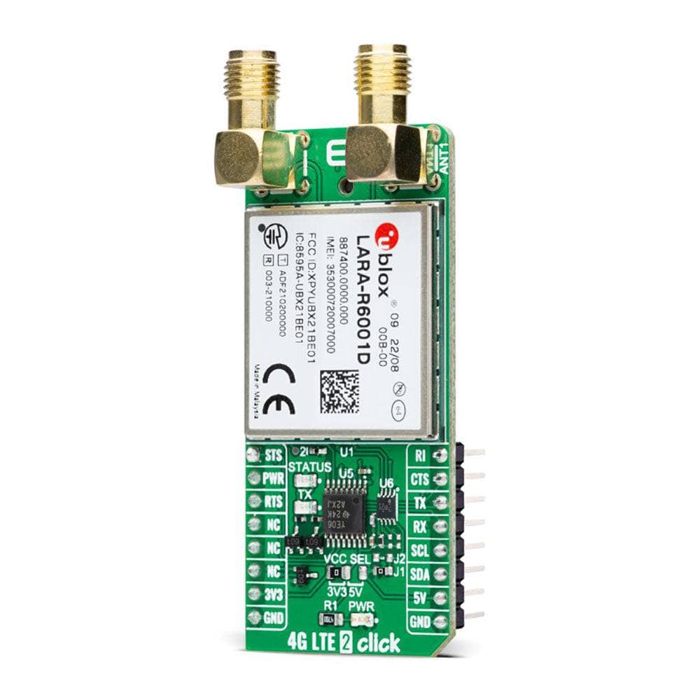
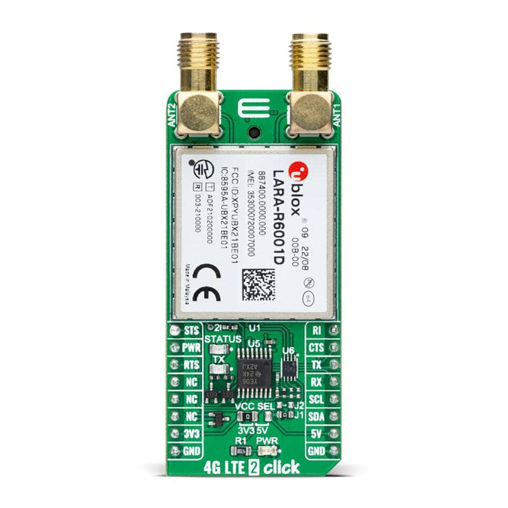
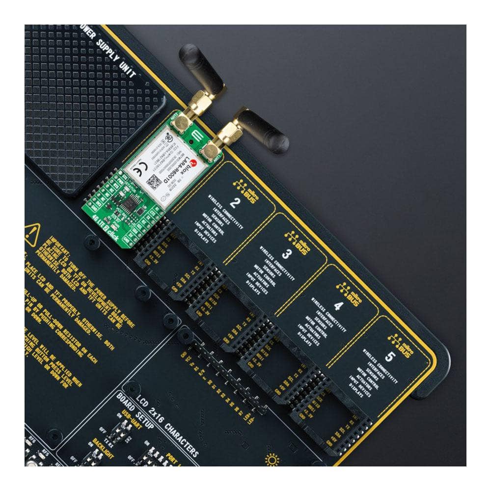
The 4G LTE 2 Data Click Board™ is a compact add-on board representing a secure-cloud multi-band solution offering universal connectivity and reliable performance. This board features the LARA-R6001D, the world’s smallest LTE Cat 1 module with global coverage and a built-in MQTT client from u-blox, representing a data-only solution. Equipped with familiar AT commands set over the UART interface, USB interface, and Network and Status indicators, the LARA-R6001D also has a comprehensive certification scheme, multi-band and multi-mode capabilities providing excellent flexibility, except for the support of voice/audio application. Taking advantage of embedded IoT protocols and security features, this Click board™ is suitable for various applications, such as device management, remote device actions, and secure FOTA updates.
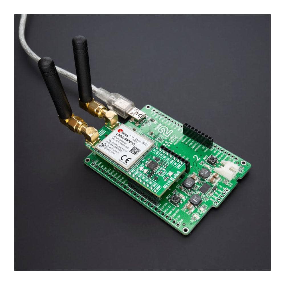
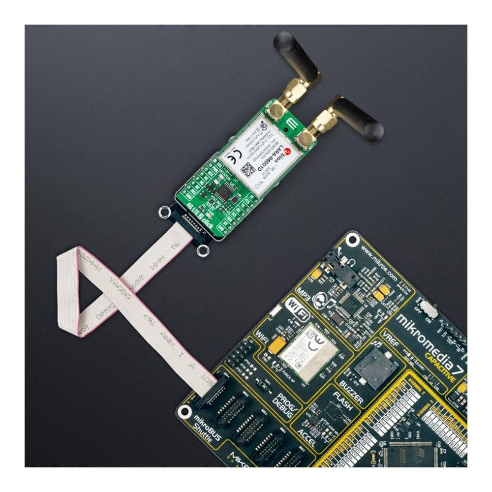
The 4G LTE 2 Data Click Board™ is supported by a mikroSDK-compliant library, which includes functions that simplify software development. This Click board™ comes as a thoroughly tested product, ready to be used on a system equipped with the mikroBUS™ socket.


How Does The 4G LTE 2 Click Board™ Work?
The 4G LTE 2 Click Board™, as its foundation, uses the LARA-R6001D, a multi-band and multi-mode module supporting LTE Cat 1 FDD and LTE Cat 1 TDD radio access technology (18 LTE bands), with 3G UMTS/HSPA and 2G GSM/GPRS/EGPRS fallback from u-blox providing the ideal solution for uncompromised global connectivity. This Click board™ represents a data-only solution with global coverage and all relevant MNO certifications, offering great flexibility except for the support of voice/audio applications. Versatile interfaces and features make the LARA-R6001D ideally suited for a wide range of applications that require medium data speed, seamless connectivity, superior coverage, low latency, and streaming data such as asset tracking, telematics, remote monitoring, point-of-sale terminals, and more.
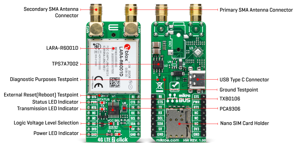
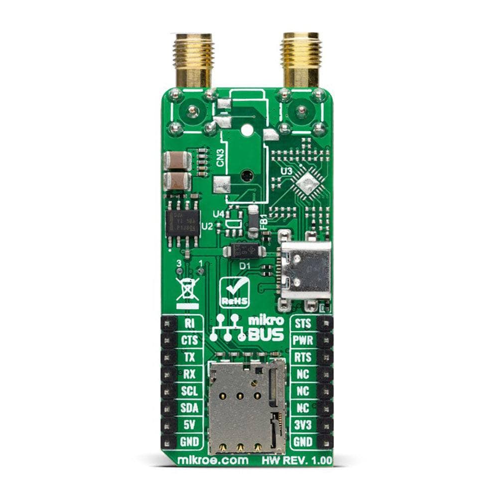
This module requires a power supply of 3.8V. Therefore, the Click board™ incorporates an integrated buck (step-down DC-DC) converter, labelled as TPS7A7002 by Texas Instruments, which provides a stable 3.8V power supply, capable of mitigating voltage drops at the input when a high current peak appears (typically at the StartUp of the device). The module Ignition (Power-On) pin, labelled as PWR and routed to the RST pin on the mikroBUS™ socket, offers a switch operation to turn ON/OFF power delivery to the LARA-R6001D.
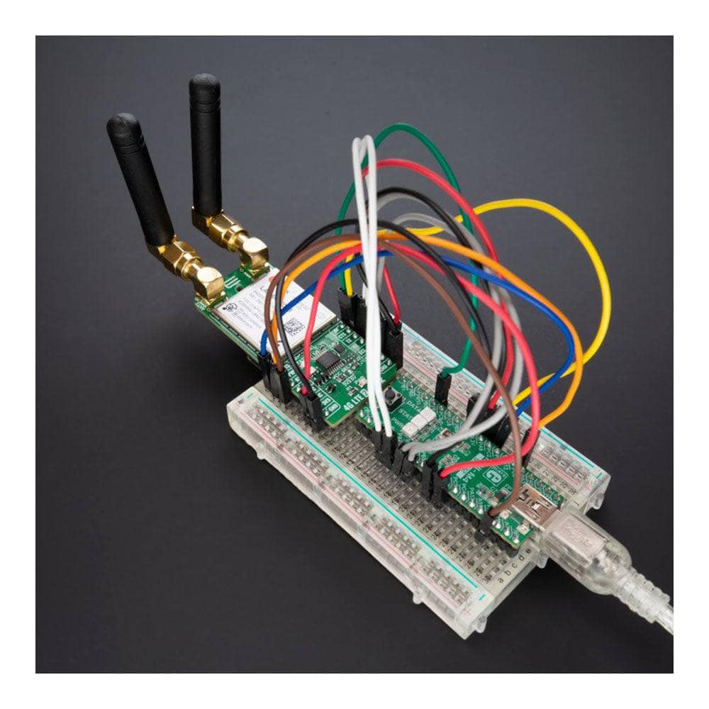
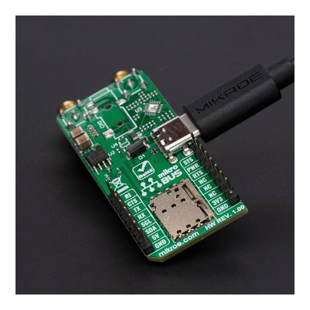
The LARA-R6001D communicates with MCU using the UART interface with commonly used UART RX and TX pins with the hardware flow control pins UART CTS, RTS, RI (Clear to Send, Ready to Send, and Ring Indicator). It operates at 115200 bps by default configuration to transmit and exchange data with the host MCU through AT commands that u-blox provides. Besides the UART interface, the LARA-R6001D also provides the possibility of using the I2C interface acting as an I2C host, which can communicate with I2C local devices following the I2C bus specifications. The 4G LTE 2 Click Board™ is also equipped with a USB type C connector, available for diagnostic purposes only. The module is a USB device and can be connected to any USB host with compatible drivers.
Among its used pins, this Click board™ also possesses two additional LED indicators: the yellow LED labelled as STATUS, routed both to the mikroBUS™ AN pin (STS) and the LED, used to indicate the status of the network connection visually, and a red LED labelled as TX used to tell the transmitting status of the module.
The LTE cellular networks use spatial multiplexing antenna technology, allowing more than one antenna to be used for better reception of the specific frequency channel. For that reason, besides the primary TX/RX antenna, this Click board™ uses a secondary diversity RX antenna, which allows better signal reception. Alongside those SMA connectors, the 4G LTE 2 Click also has a Nano-SIM card slot that provides multiple connections and interface options alongside several test points labelled from TP1 to TP3, enabling easy reboot and testing of the module.
The 4G LTE 2 Click Board™ can operate with both 3.3V and 5V logic voltage levels selected via the VCC SEL jumper. This way, it is allowed for both 3.3V and 5V capable MCUs to use the communication lines properly. However, the Click board™ comes equipped with a library containing easy-to-use functions and an example code that can be used, as a reference, for further development.
SPECIFICATIONS
| Type | 2G GPRS,4G LTE,GSM/LTE |
| Applications | Can be used for device management, remote device actions, and secure FOTA updates |
| On-board modules | LARA-R6001D - LTE Cat 1 module with global coverage from u-blox |
| Key Features | Universal connectivity, multi-mode, secure cloud, receive-diversity for reliable performance in difficult conditions, MNO certifications, professional grade, global region, compatible with u-blox services, various interfaces, and more |
| Interface | I2C,UART,USB |
| Compatibility | mikroBUS |
| Click board size | L (57.15 x 25.4 mm) |
| Input Voltage | 3.3V or 5V |
PINOUT DIAGRAM
This table shows how the pinout of the 4G LTE 2 Click Board™ - Data corresponds to the pinout on the mikroBUS™ socket (the latter shown in the two middle columns).
| Notes | Pin | Pin | Notes | ||||
|---|---|---|---|---|---|---|---|
| Module Status | STS | 1 | AN | PWM | 16 | RI | UART RI |
| Power-ON | PWR | 2 | RST | INT | 15 | CTS | UART CTS |
| UART RTS | RTS | 3 | CS | RX | 14 | TX | UART TX |
| NC | 4 | SCK | TX | 13 | RX | UART RX | |
| NC | 5 | MISO | SCL | 12 | SCL | I2C Clock | |
| NC | 6 | MOSI | SDA | 11 | SDA | I2C Data | |
| Power Supply | 3.3V | 7 | 3.3V | 5V | 10 | 5V | Power Supply |
| Ground | GND | 8 | GND | GND | 9 | GND | Ground |
ONBOARD SETTINGS AND INDICATORS
| Label | Name | Default | Description |
|---|---|---|---|
| LD1 | PWR | - | Power LED Indicator |
| LD2 | TX | - | Transmission LED Indicator |
| LD3 | STATUS | - | Status LED Indicator |
| JP1 | VCC SEL | Left | Logic Level Voltage Selection 3V3/5V: Left position 3V3, Right position 5V |
| TP1 | 1 | - | Ground Testpoint |
| TP2 | 2 | - | External Reset (Reboot) Testpoint |
| TP3 | 3 | - | Diagnostic Purposes Testpoint |
4G LTE 2 CLICK - DATA ELECTRICAL SPECIFICATIONS
| Description | Min | Typ | Max | Unit |
|---|---|---|---|---|
| Supply Voltage | 3.3 | - | 5 | V |
| LTE Operating Frequency Range (Uplink) | 663 | - | 2750 | MHz |
| LTE Operating Frequency Range (Downlink) | 617 | - | 2690 | MHz |
| Operating Temperature Range | -20 | +25 | +65 | °C |
Software Support
We provide a library for the 4G LTE 2 Click Board™ as well as a demo application (example), developed using MikroElektronika compilers. The demo can run on all the main MikroElektronika development boards.
The package can be downloaded/installed directly from NECTO Studio The package Manager (recommended), downloaded from our LibStock™ or found on the MikroE Github account.
Library Description
This library contains API for the 4G LTE 2 Click Board™ driver.
Key functions
-
c4glte2data_set_power_stateThis function sets a desired power state by toggling PWR pin with a specific time for high state. -
c4glte2data_set_sim_apnThis function sets APN for sim card. -
c4glte2data_send_sms_textThis function sends text message to a phone number.
Example Description
Application example shows device capability of connecting to the network and sending SMS or TCP/UDP messages using standard "AT" commands.
void application_task ( void )
 {
     switch ( example_state )
     {
         case C4GLTE2DATA_CONFIGURE_FOR_NETWORK:
         {
             if ( C4GLTE2DATA_OK == c4glte2data_configure_for_network( ) )
             {
                 example_state = C4GLTE2DATA_WAIT_FOR_CONNECTION;
             }
             break;
         }
         case C4GLTE2DATA_WAIT_FOR_CONNECTION:
         {
             if ( C4GLTE2DATA_OK == c4glte2data_check_connection( ) )
             {
                 example_state = C4GLTE2DATA_CONFIGURE_FOR_EXAMPLE;
             }
             break;
         }
         case C4GLTE2DATA_CONFIGURE_FOR_EXAMPLE:
         {
             if ( C4GLTE2DATA_OK == c4glte2data_configure_for_example( ) )
             {
                 example_state = C4GLTE2DATA_EXAMPLE;
             }
             break;
         }
         case C4GLTE2DATA_EXAMPLE:
         {
             c4glte2data_example( );
             break;
         }
         default:
         {
             log_error( &logger, " Example state." );
             break;
         }
     }
 }
The complete application code, and ready to use projects can be installed directly from NECTO Studio. The package Manager (recommended), downloaded from our LibStock™ or found on the MikroE Github account.
Other MikroE Libraries used in the example:
- MikroSDK.Board
- MikroSDK.Log
- Click.4GLTE2Data
Additional Notes and Information
Depending on the development board you are using, you may need USB UART Click Board™, USB UART 2 Click or RS232 Click to connect to your PC, for development systems with no UART to USB interface available on the board. UART terminal is available in all MikroElektronika compilers.
MIKROSDK
The 4G LTE 2 Click Board™ is supported with mikroSDK - MikroElektronika Software Development Kit. To ensure proper operation of mikroSDK compliant Click board™ demo applications, mikroSDK should be downloaded from the LibStock and installed for the compiler you are using.
4G LTE 2 Data Click Board
Frequently Asked Questions
Have a Question?
Be the first to ask a question about this.