


Mikroelektronika d.o.o.
Step Down 3 Click Board™
Step Down 3 Click Board™
SKU: MIKROE-5169
Couldn't load pickup availability


Overview
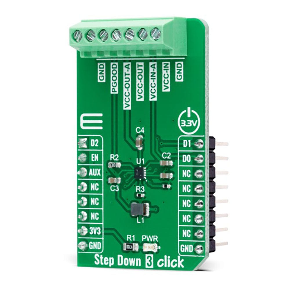
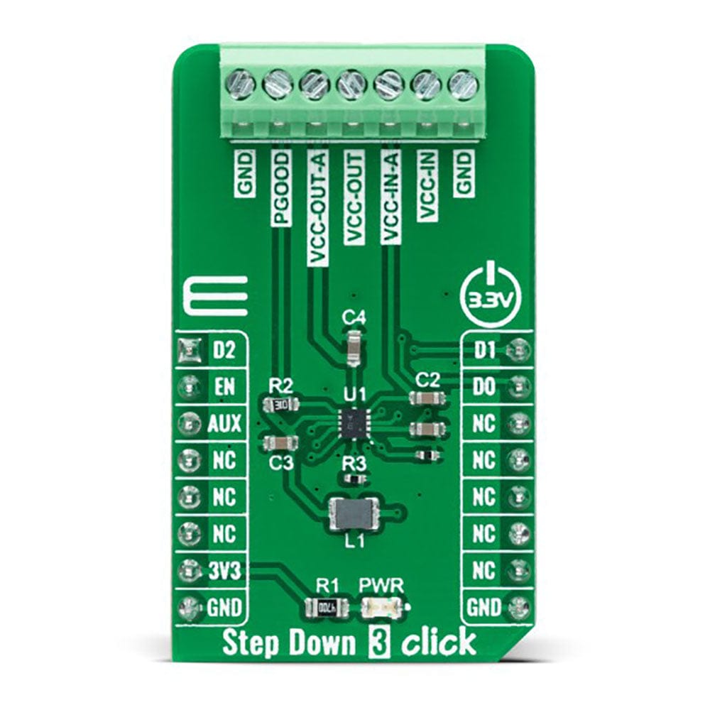
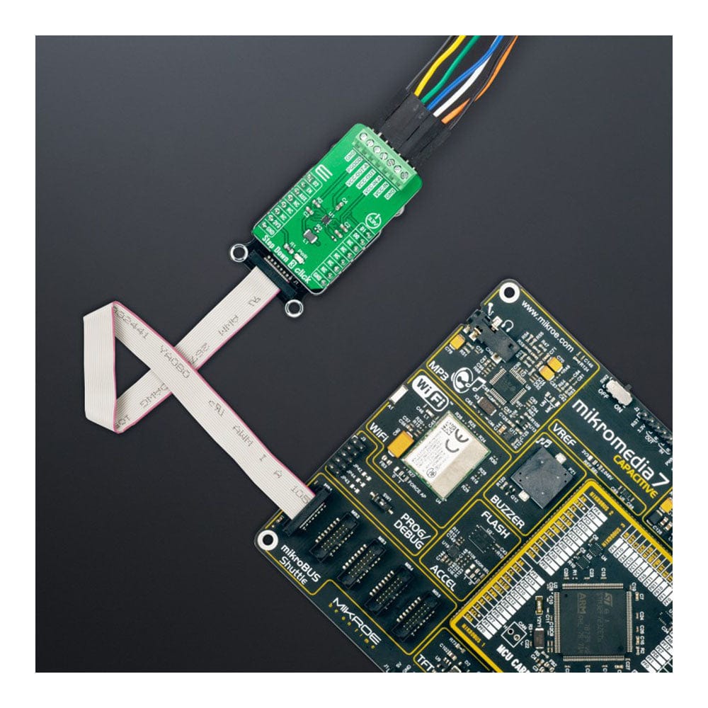
The Step Down 3 Click Board™ is a compact add-on board that steps down the voltage from its input to its output. This board features the ST1PS03, a nano-quiescent miniaturized synchronous step-down converter with a load switch from STMicroelectronics. The ST1PS03 can provide up to 400mA output current with an input voltage ranging from 1.8V to 5.5V, specifically designed for applications where high efficiency is crucial. It also embeds a controlled switch accessible from auxiliary channel input to supply a subsystem, output voltage from 1.6V to 3.3V set using three digital control inputs, and a Power Good signal to indicate stabilized output voltages. This Click Board™ is suitable for power conversion solutions in personal tracking monitors, energy harvesting, industrial sensors, portable low-power devices, and more.
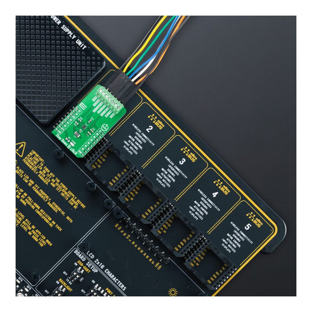
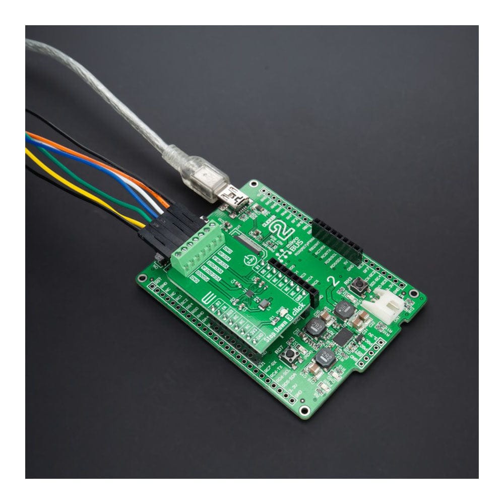
The Step Down 3 Click Board™ is supported by a mikroSDK compliant library, which includes functions that simplify software development. This Click board™ comes as a fully tested product, ready to be used on a system equipped with the mikroBUS™ socket.
Downloads
How Does The Step Down 3 Click Board™ Work?
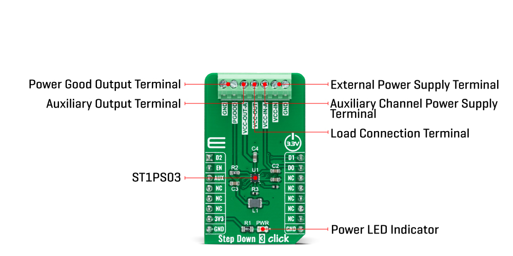
The Step Down 3 Click Board™ is based on the ST1PS03, an ultra-low quiescent new generation buck converter from STMicroelectronics. The ST1PS03 targets a small quiescent current consumption, and it guarantees high-efficiency operation even down to a few microampere loads. It can provide up to 400mA output current with an output voltage from 1.6V to 3.3V on the VCC-OUT terminal, selectable using three digital control pins routed to the INT, PWM, and AN pins of the mikroBUS™ socket, and an input voltage ranging from 1.8V to 5.5V appliable on VCC-IN terminal.
The ST1PS03 is based on a hysteretic comparator that senses the coil ripple current, held constant in all operation modes. The ST1PS03 changes the switching frequency depending on the input supply voltage to maintain a continuous ripple current on the selected coil. It has a seamless transition between PFM (pulse frequency modulation) and PWM (pulse width modulation) mode with low ripple and good load transient response. During PWM mode (heavy load), the device operates in continuous conduction up to 400mA and a switching frequency of 2MHz maximum.
The device enters 100% duty cycle operation if the input voltage comes close to the selected output voltage. The regulator is turned OFF during this mode, and the output pin is directly connected to the input pin through the internal high-side MOSFET. Once the input voltage exceeds the 100% duty cycle, the device restarts to switch and regulates the output voltage again. This Click board™ also has a Power Good comparator which monitors the selected output voltage and provides information on the appropriate PGOOD terminal.
The Step Down 3 Click Board™ communicates with MCU using several GPIO pins. The AUX pin routed to the CS pin of the mikroBUS™ socket controls the auxiliary output terminal labelled as VCC-OUT-A. It provides the same regulated voltage level as VCC-IN-a input voltage, less drop on the load switch circuitry when the AUX pin and EN pin, routed to the RST pin of the mikroBUS™ socket, are tied high. The VCC-OUT-A terminal allows connecting/disconnecting the other system load to the output of the ST1PS03.
The Step Down 3 Click Board™ can be operated only with a 3.3V logic voltage level. The board must perform appropriate logic voltage level conversion before using MCUs with different logic levels. However, the Click board™ comes equipped with a library containing functions and an example code that can be used, as a reference, for further development.
SPECIFICATIONS
| Type | Buck |
| Applications | Can be used for power conversion solutions in personal tracking monitors, energy harvesting, industrial sensors, portable low power devices, and more |
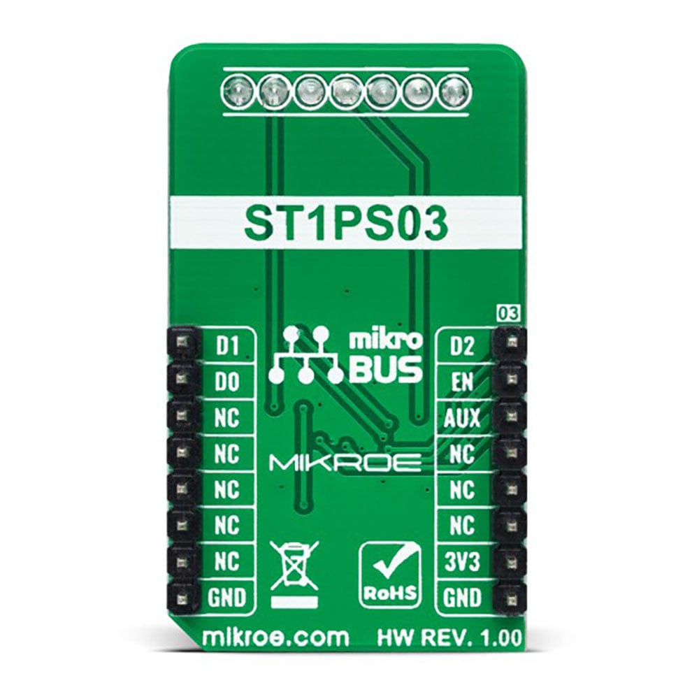
| On-board modules | ST1PS03 - ultra-low quiescent new generation buck converter from STMicroelectronics |
| Key Features | Nano-quiescent synchronous step-down converter, output voltage selection, Power Good indicator, load switch controlled by auxiliary channel, undervoltage lockout, low power consumption, high efficiency, and more |
| Interface | GPIO |
| Compatibility | mikroBUS |
| Click board size | M (42.9 x 25.4 mm) |
| Input Voltage | 3.3V |
PINOUT DIAGRAM
This table shows how the pinout of the Step Down 3 Click Board™ corresponds to the pinout on the mikroBUS™ socket (the latter shown in the two middle columns).
| Notes | Pin | Pin | Notes | ||||
|---|---|---|---|---|---|---|---|
| Output Voltage Selection Pin 2 | D2 | 1 | AN | PWM | 16 | D1 | Output Voltage Selection Pin 1 |
| Device Enable | EN | 2 | RST | INT | 15 | D0 | Output Voltage Selection Pin 0 |
| Auxiliary | AUX | 3 | CS | RX | 14 | NC | |
| NC | 4 | SCK | TX | 13 | NC | ||
| NC | 5 | MISO | SCL | 12 | NC | ||
| NC | 6 | MOSI | SDA | 11 | NC | ||
| Power Supply | 3.3V | 7 | 3.3V | 5V | 10 | NC | |
| Ground | GND | 8 | GND | GND | 9 | GND | Ground |
ONBOARD SETTINGS AND INDICATORS
| Label | Name | Default | Description |
|---|---|---|---|
| LD1 | PWR | - | Power LED Indicator |
STEP DOWN 3 CLICK ELECTRICAL SPECIFICATIONS
| Description | Min | Typ | Max | Unit |
|---|---|---|---|---|
| Supply Voltage VCC | - | 3.3 | - | V |
| External Supply Voltage VCC-IN | 1.8 | - | 5.5 | V |
| Output Voltage VCC-OUT | 1.6 | - | 3.3 | V |
| Auxiliary Input Voltage VCC-IN-A | 0 | - | 5.5 | V |
| Auxiliary Output Current VCC-OUT-A | - | - | 100 | mA |
| Switching Frequency | - | - | 2 | MHz |
| Operating Temperature Range | -40 | +25 | +120 | °C |
| General Information | |
|---|---|
Part Number (SKU) |
MIKROE-5169
|
Manufacturer |
|
| Physical and Mechanical | |
Weight |
0.02 kg
|
| Other | |
EAN |
8606027388545
|
Frequently Asked Questions
Have a Question?
Be the first to ask a question about this.