


Mikroelektronika d.o.o.
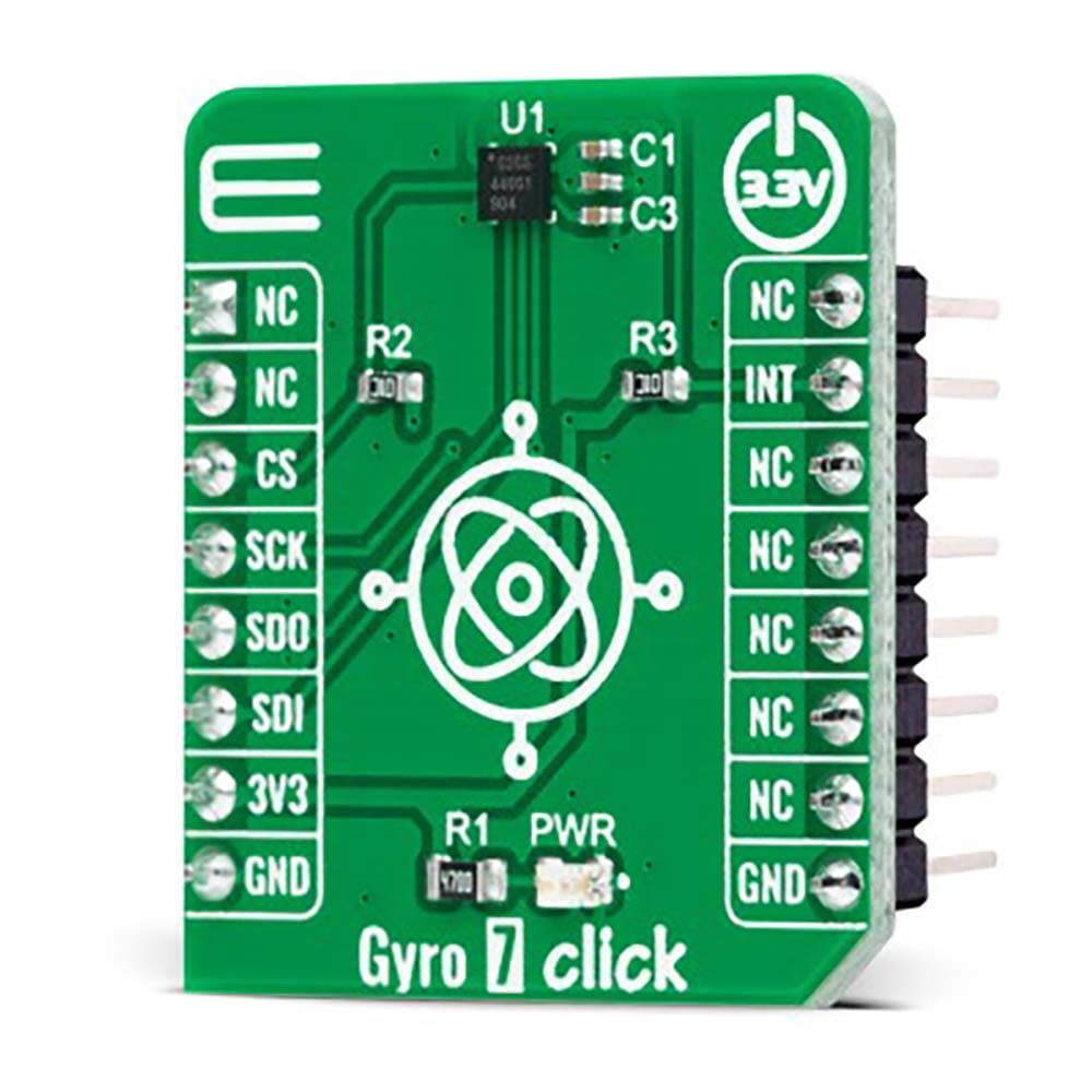
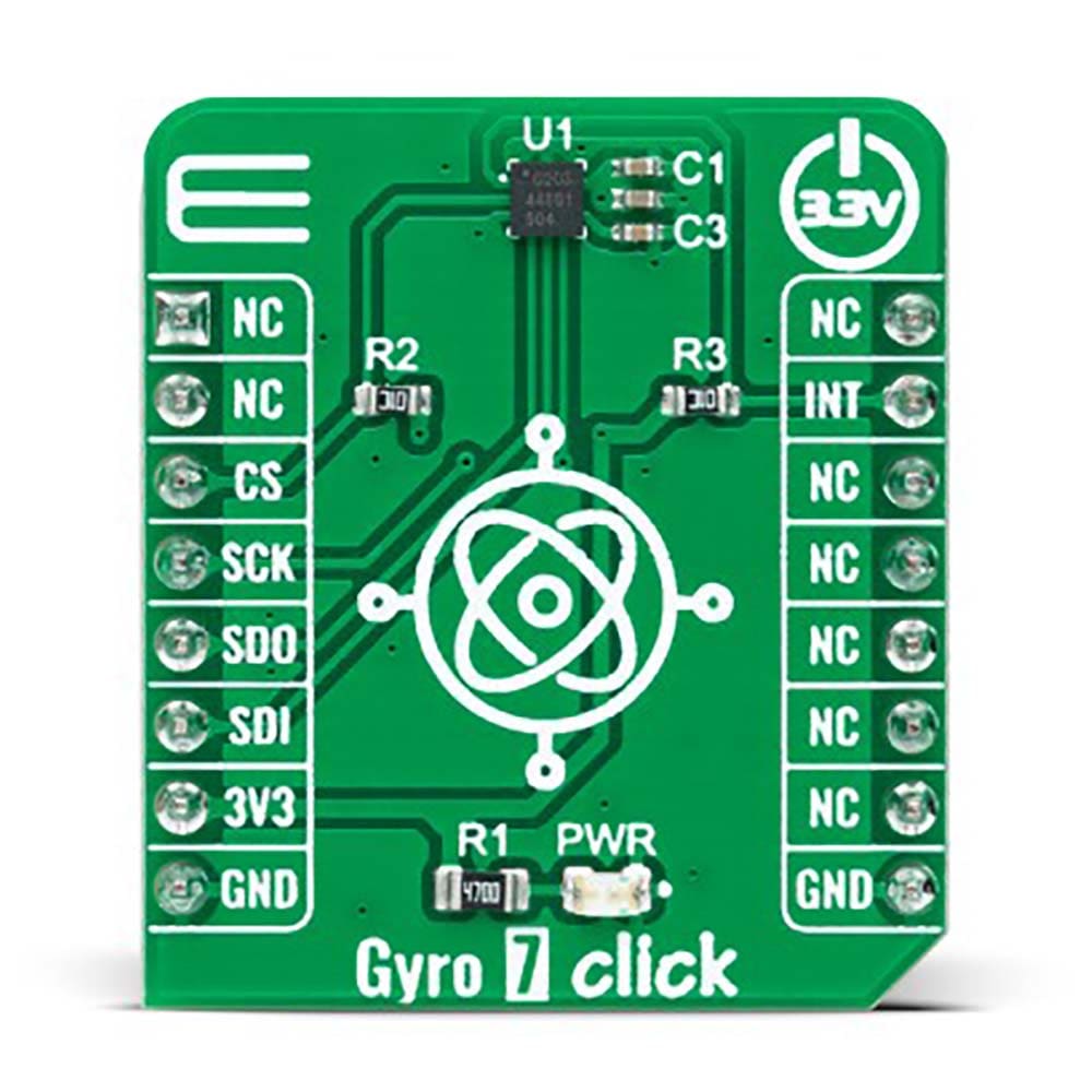
Gyro 7 Click Board™
Gyro 7 Click Board™
SKU: MIKROE-5145
Couldn't load pickup availability


Overview
The Gyro 7 Click Board™ is a compact add-on board that contains a high-performance gyroscope. This board features the ICG-1020S, a dual-axis MEMS angular rate sensor (gyroscope) from TDK InvenSense. The ICG-1020S provides extremely low RMS noise as well as noise density. The high-resolution gyroscope supports a full-scale programmable range of ±46.5dps to ±374dps, a fast sample rate at up to 32kHz, an SPI serial interface, and extremely low power consumption. This Click board™ is designed for optical image stabilization (OIS) applications.
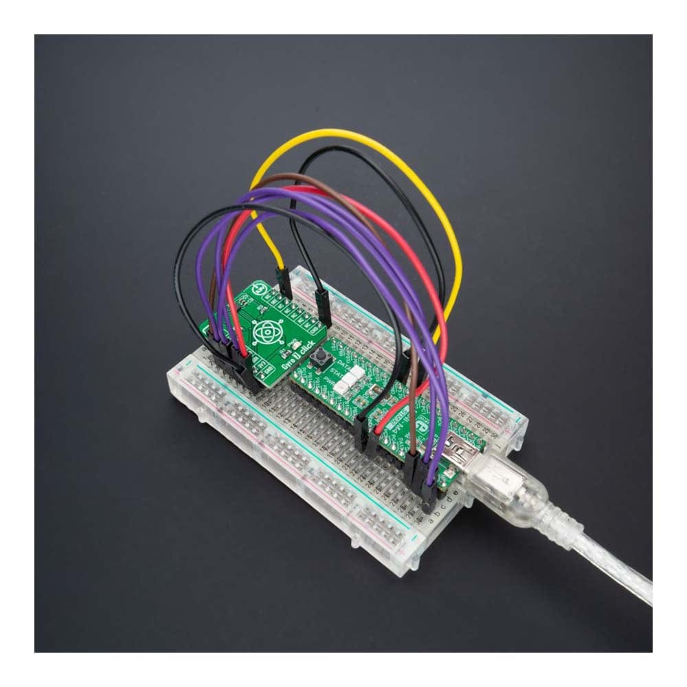
The Gyro 7 Click Board™ is supported by a mikroSDK compliant library, which includes functions that simplify software development. This Click board™ comes as a fully tested product, ready to be used on a system equipped with the mikroBUS™ socket.
Downloads
How Does The Gyro 7 Click Board™ Work?
The Gyro 7 Click Board™ as its foundation uses the ICG-1020S, a high-performance 2-axis gyroscope from TDK InvenSense. The ICG-1020S is highly configurable with a full-scale programmable range from ±46.5dps to ±374dps. The single structure vibratory MEMS rate gyroscope detects the X- and Y-axis rotation. When the gyroscope is rotated about any sense axes, the Coriolis effect causes a detected vibration. The resulting signal is amplified, demodulated, and filtered to produce a proportional voltage to the angular rate. With its 2-axis integration, the Gyro 7 Click Board™ allows you to design it into an optical image stabilization (OIS) application.
Two-axis MEMS rate gyroscope sensor, the ICG-1020S, comes with integrated 16-bit ADCs and signal conditioning with two axes XY configuration. After the signal is digitized, data is processed through a digital filter and output through sensor data registers. Besides, the ICG-1020S is also characterized by high resolution and low RMS noise, noise density, a fast sample rate at up to 32kHz, and low power consumption.
The Gyro 7 Click Board™ communicates with MCU through a register-selectable standard SPI interface that enables high clock speed up to 20MHz, supporting the two most common SPI modes, SPI Mode 0 and 3. Other blocks include onboard clocking, temperature compensation, and bias circuits. The sensor data registers contain the latest gyro data, and they are read-only registers accessible via the serial interface. Data from these registers may be read anytime. It also possesses an additional interrupt signal, routed on the INT pin of the mikroBUS™ socket labelled as INT, indicating when a specific interrupt event occurs.
The Gyro 7 Click Board™ can be operated only with a 3.3V logic voltage level. The board must perform appropriate logic voltage level conversion before using MCUs with different logic levels. However, the Click board™ comes equipped with a library containing functions and an example code that can be used, as a reference, for further development.
SPECIFICATIONS
| Type | Motion |
| Applications | The Gyro 7 Click Board™ can be used for optical image stabilization (OIS) applications |
| On-board modules | ICG-1020S - dual-axis MEMS angular rate sensor (gyroscope) from TDK InvenSense |
| Key Features | Low power consumption, full-scale programmable range up to ±374dps, integrated 16-bit ADCs, user-programmable digital filters, interrupt, high performance, reliability, and more |
| Interface | SPI |
| Compatibility | mikroBUS |
| Click board size | S (28.6 x 25.4 mm) |
| Input Voltage | 3.3V |
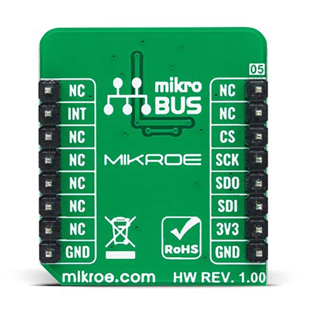
PINOUT DIAGRAM
This table shows how the pinout of the Gyro 7 Click Board™ corresponds to the pinout on the mikroBUS™ socket (the latter shown in the two middle columns).
| Notes | Pin | Pin | Notes | ||||
|---|---|---|---|---|---|---|---|
| NC | 1 | AN | PWM | 16 | NC | ||
| NC | 2 | RST | INT | 15 | INT | Interrupt | |
| SPI Chip Select | CS | 3 | CS | RX | 14 | NC | |
| SPI Clock | SCK | 4 | SCK | TX | 13 | NC | |
| SPI Data OUT | SDO | 5 | MISO | SCL | 12 | NC | |
| SPI Data IN | SDI | 6 | MOSI | SDA | 11 | NC | |
| Power Supply | 3.3V | 7 | 3.3V | 5V | 10 | NC | |
| Ground | GND | 8 | GND | GND | 9 | GND | Ground |
ONBOARD SETTINGS AND INDICATORS
| Label | Name | Default | Description |
|---|---|---|---|
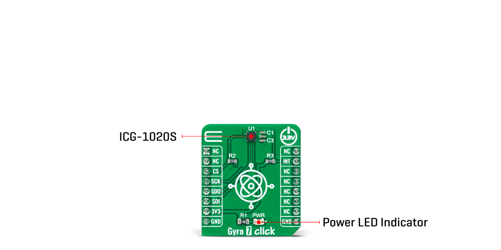
| LD1 | PWR | - | Power LED Indicator |
GYRO 7 CLICK ELECTRICAL SPECIFICATIONS
| Description | Min | Typ | Max | Unit |
|---|---|---|---|---|
| Supply Voltage | - | 3.3 | - | V |
| Full-Scale Range | ±46.5 | - | ±374 | dps |
| Sensitivity | 87.5 | - | 700 | LSB/(º/s) |
| Resolution | - | 16 | - | bits |
| Operating Temperature Range | -40 | +25 | +85 | °C |
| General Information | |
|---|---|
Part Number (SKU) |
MIKROE-5145
|
Manufacturer |
|
| Physical and Mechanical | |
Weight |
0.02 kg
|
| Other | |
EAN |
8606027388828
|
Frequently Asked Questions
Have a Question?
Be the first to ask a question about this.