Key Features
Overview
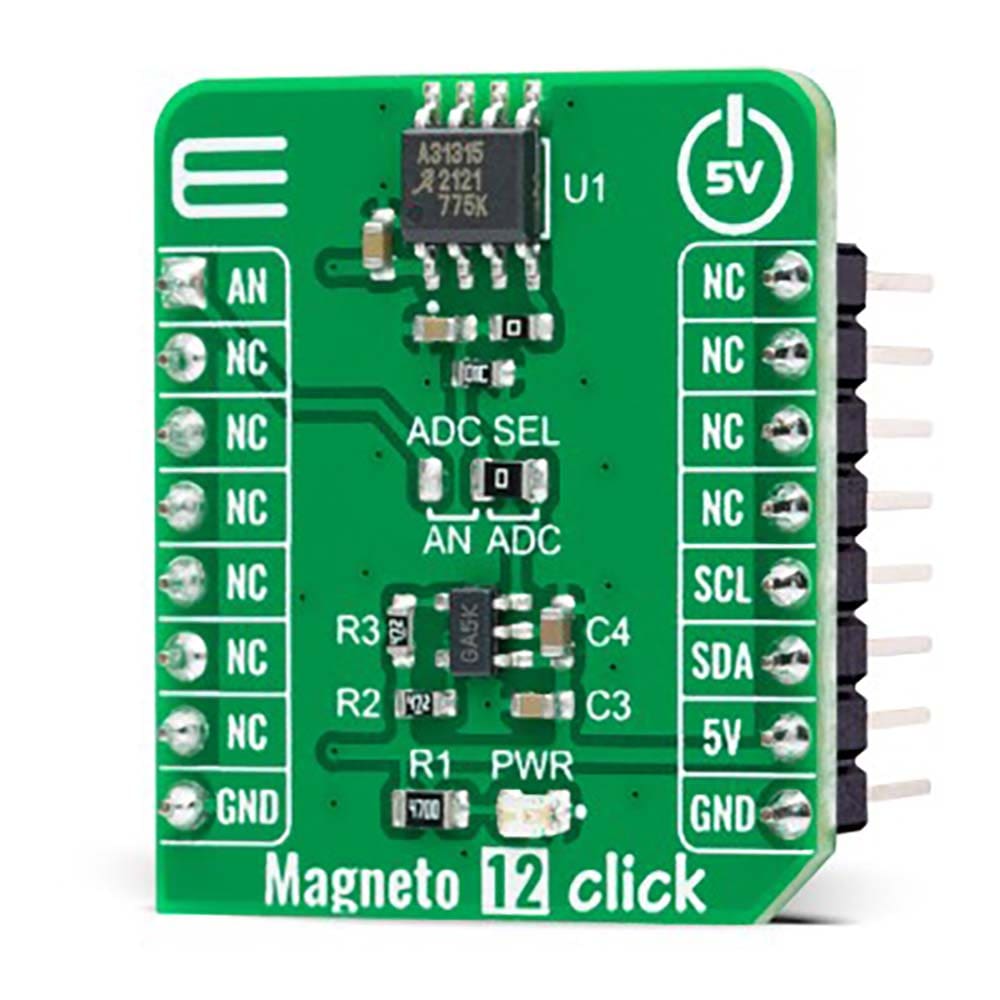
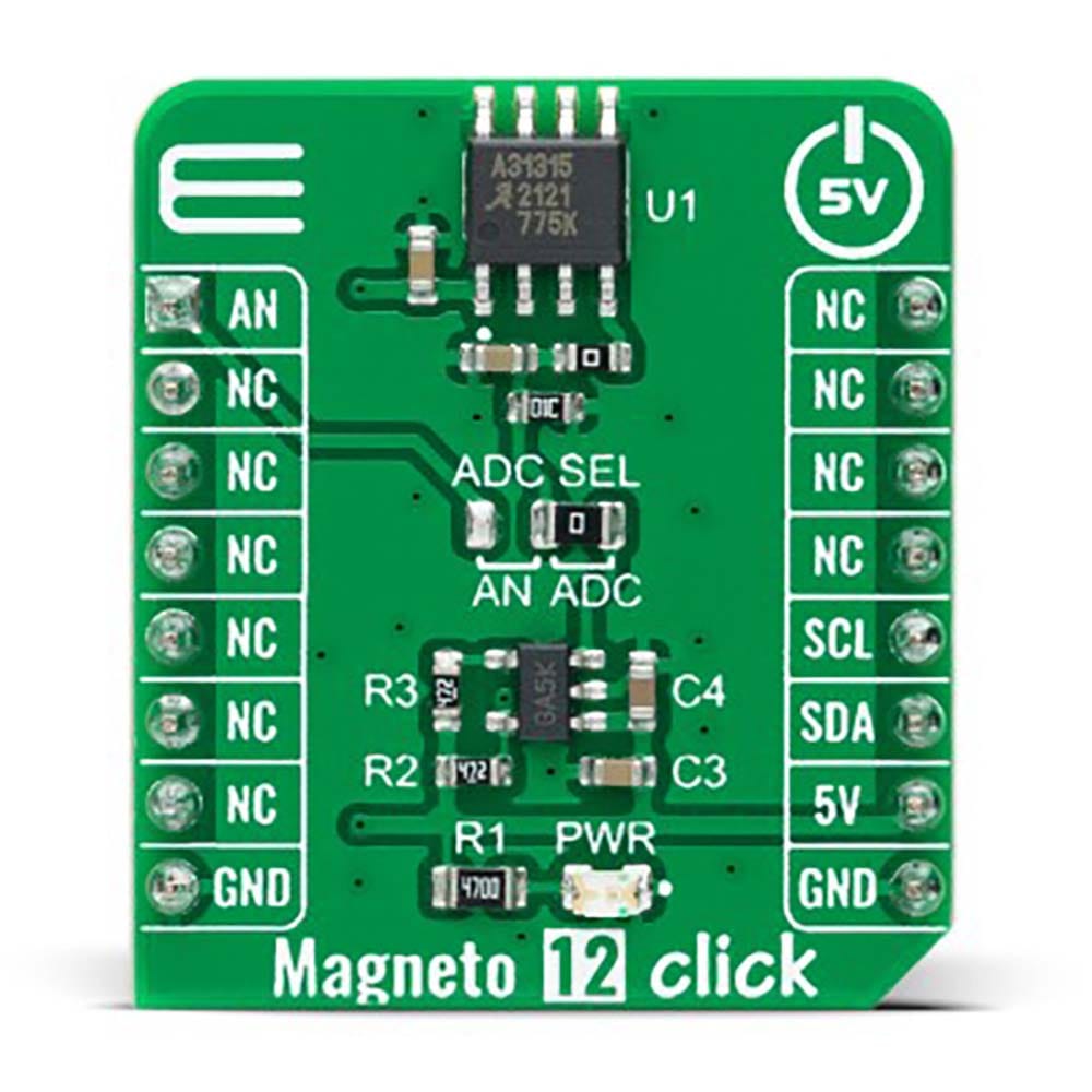
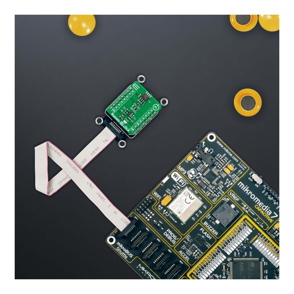
The Magneto 12 Click Board™ is a compact add-on board that contains an accurate and reliable magnetic sensing device. This board features the A31315, a magnetic position sensor designed for on- and off-axis rotary and linear stroke position measurement from Allegro Microsystems. This sensor integrates vertical and planar Hall-effect elements with precision temperature-compensating circuitry to detect two out of three magnetic field components (X and Y). Using configurable signal processing (the user is allowed to process the output signal in analog or digital form), linearization and angle calculation allows the A31315 to accurately resolve the absolute rotary (full 360° and short-stroke <360°) or linear position of a moving magnetic target. This Click board™ is suitable for position sensing applications in automotive, industrial, and consumer applications.
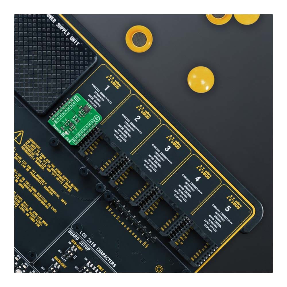
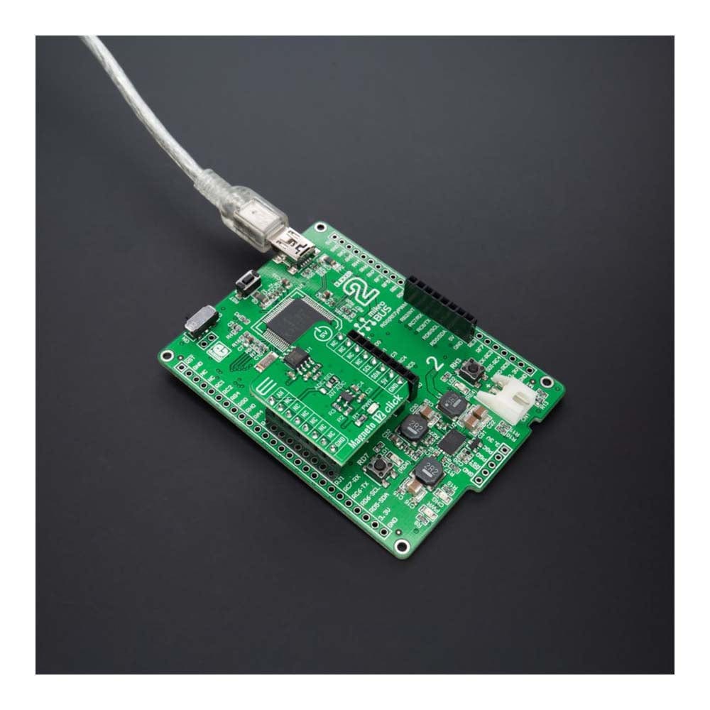
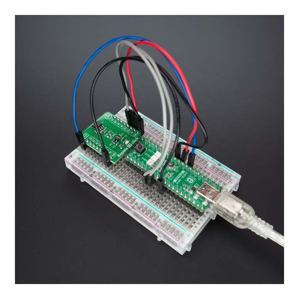
The Magneto 12 Click Board™ is supported by a mikroSDK compliant library, which includes functions that simplify software development. This Click board™ comes as a fully tested product, ready to be used on a system equipped with the mikroBUS™ socket.
Downloads
How Does The Magneto 12 Click Board™ Work?
The Magneto 12 Click Board™ as its foundation uses the A31315, a magnetic position sensor from Allegro Microsystems. This sensor integrates vertical and planar Hall-effect elements with precision temperature-compensating circuitry to detect two out of three magnetic field components (X and Y). Using configurable signal processing, linearization, and angle calculation allows the A31315 to accurately resolve the absolute rotary (full 360° and short-stroke <360°) or linear position of a moving magnetic target.
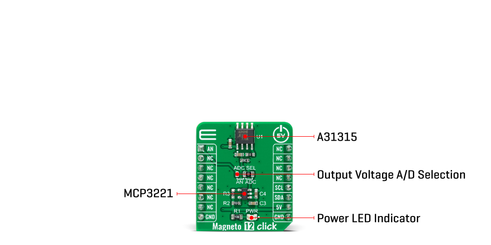
The A31315 features a ratiometric analog interface to output the angle between the two factory-selected axes (X and Y). When using the analog mode of the A31315, the capacitance is provided for the stability of the output. A load resistor R4 also provides a known diagnostic state in a line break or device tri-state event. A series resistor R5 can be placed (default resistor value is 0Ω) before the capacitance C2 to create a low-pass filter for additional filtering and lower noise. However, caution should be taken, as this could also reduce the operating output voltage based on the ratio of the filter resistor and the load resistance.
The Magneto 12 Click Board™ possesses two ways to communicate with the MCU. The analog output signal of the A31315 can be converted to a digital value using MCP3221, a successive approximation A/D converter with a 12-bit resolution from Microchip using a 2-wire I2C compatible interface, or can be sent directly to an analog pin of the mikroBUS™ socket labelled as AN. The MCP3221 provides one single-ended input with low power consumption, a low maximum conversion current, and a Standby current of 250μA and 1μA, respectively. Data can be transferred at rates of up to 100kbit/s in the Standard and 400kbit/s in the Fast Mode. Selection can be performed by onboard SMD jumper labelled as ADC SEL, setting it to an appropriate position marked as AN and ADC.
The Magneto 12 Click Board™ can be operated only with a 5V logic voltage level. The board must perform appropriate logic voltage level conversion before using MCUs with different logic levels. However, the Click board™ comes equipped with a library containing functions and an example code that can be used, as a reference, for further development.
SPECIFICATIONS
| Type | Magnetic |
| Applications | The Magneto 12 Click Board™ can be used for position sensing applications in automotive, industrial, and consumer applications |
| On-board modules | A31315 - magnetic position sensor from Allegro Microsystems |
| Key Features | Highly accurate 360° and short stroke (360°) rotary applications, detects two out of three magnetic field components, ratiometric analog output, high reliability, possibility of signal processing in analog and digital form, and more |
| Interface | Analog,I2C |
| Compatibility | mikroBUS |
| Click board size | S (28.6 x 25.4 mm) |
| Input Voltage | 5V |
PINOUT DIAGRAM
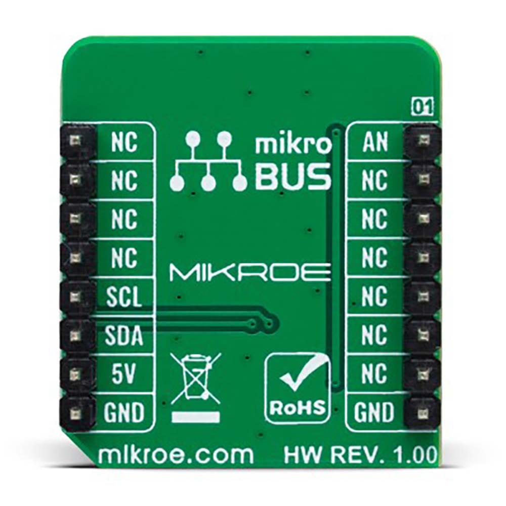
This table shows how the pinout of the Magneto 12 Click Board™ corresponds to the pinout on the mikroBUS™ socket (the latter shown in the two middle columns).
| Notes | Pin |  |
Pin | Notes | |||
|---|---|---|---|---|---|---|---|
| Analog Signal | AN | 1 | AN | PWM | 16 | NC | |
| NC | 2 | RST | INT | 15 | NC | ||
| NC | 3 | CS | RX | 14 | NC | ||
| NC | 4 | SCK | TX | 13 | NC | ||
| NC | 5 | MISO | SCL | 12 | SCL | I2C Clock | |
| NC | 6 | MOSI | SDA | 11 | SDA | I2C Data | |
| NC | 7 | 3.3V | 5V | 10 | 5V | Power Supply | |
| Ground | GND | 8 | GND | GND | 9 | GND | Ground |
ONBOARD SETTINGS AND INDICATORS
| Label | Name | Default | Description |
|---|---|---|---|
| LD1 | PWR | - | Power LED Indicator |
| JP1 | ADC SEL | Right | Output Voltage A/D Selection AN/ADC: Left position AN, Right position ADC |
MAGNETO 12 CLICK ELECTRICAL SPECIFICATIONS
| Description | Min | Typ | Max | Unit |
|---|---|---|---|---|
| Supply Voltage | - | 5 | - | V |
| Maximum Magnetic Flux Density | - | - | 1000 | G |
| Rotation Angle Range | 0 | - | 360 | deg |
| Resolution | - | 12 | - | bit |
| Operating Temperature Range | -40 | +25 | +120 | °C |
| General Information | |
|---|---|
Part Number (SKU) |
MIKROE-4991
|
Manufacturer |
|
| Physical and Mechanical | |
Weight |
0.02 kg
|
| Other | |
Country of Origin |
|
HS Code Customs Tariff code
|
|
EAN |
8606027389214
|
Warranty |
|
Frequently Asked Questions
Have a Question?
Be the first to ask a question about this.

