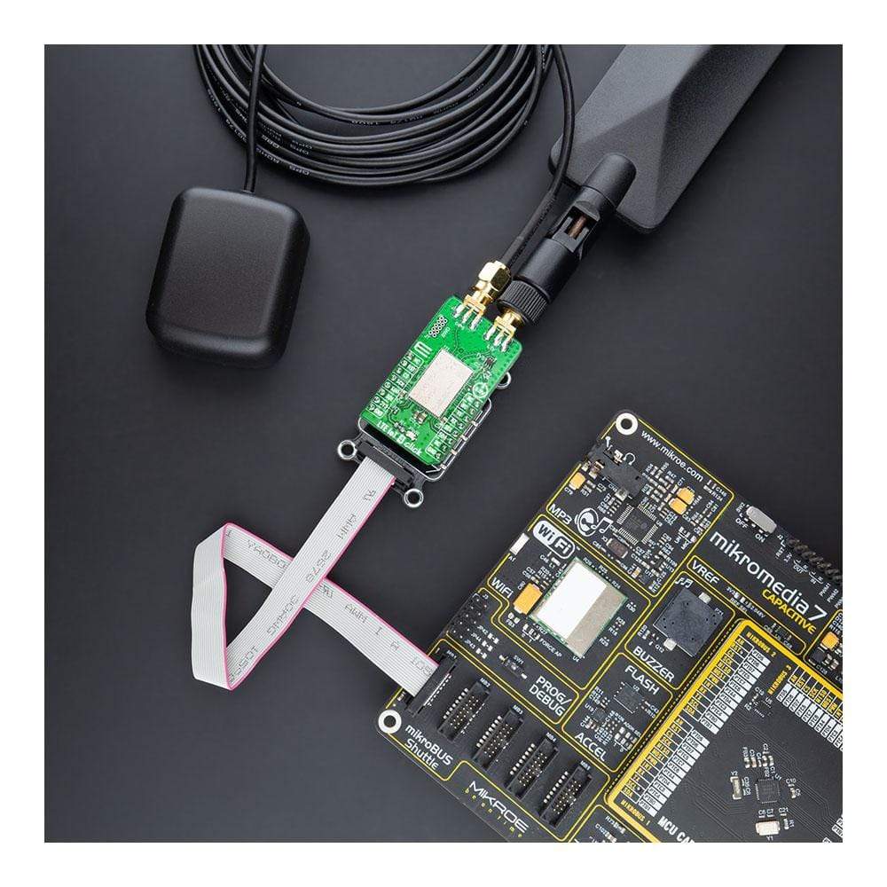
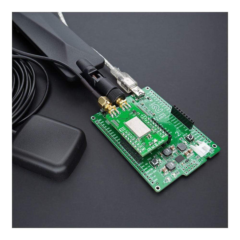
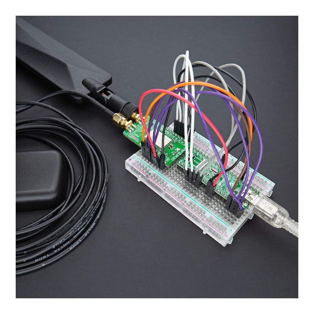
LTE IoT 4 Click Board
Overview
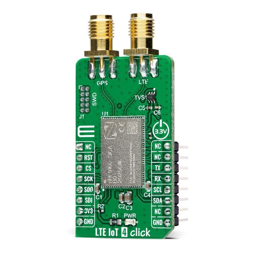
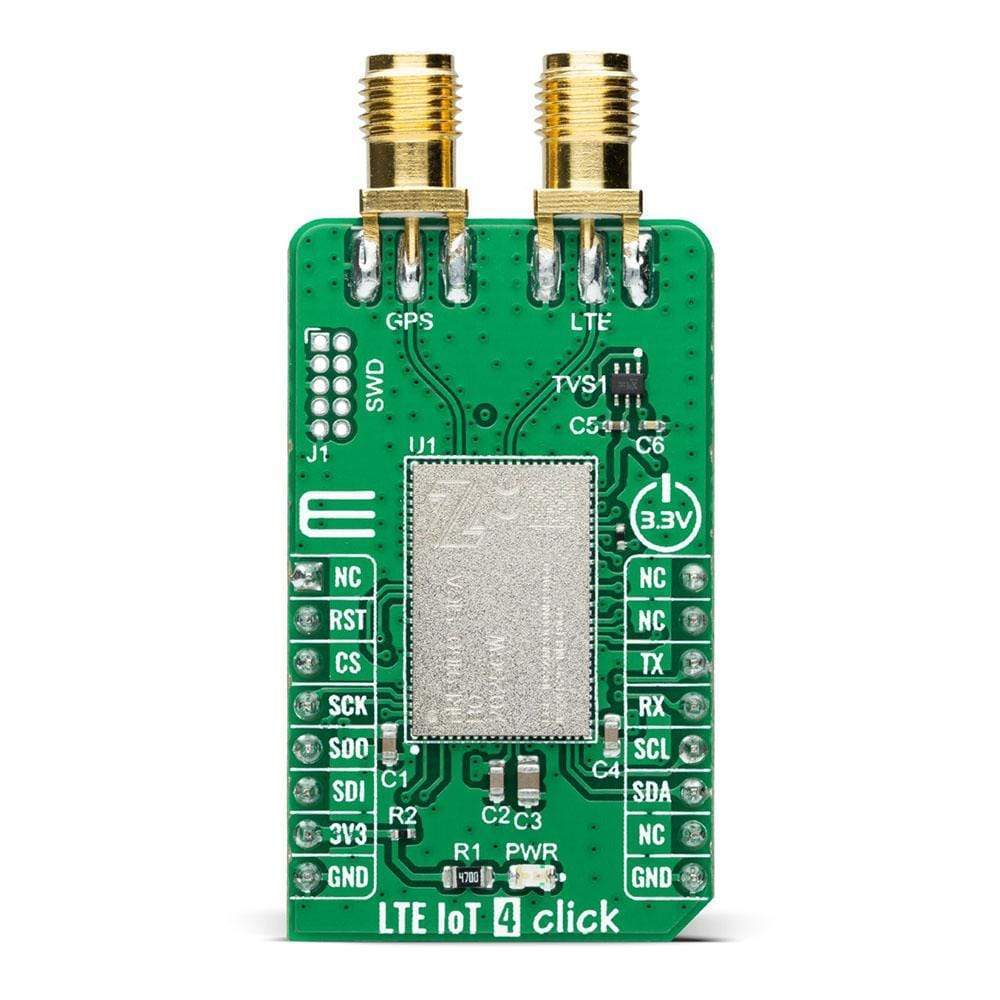
The LTE IoT 4 Click Board™ is a compact add-on board that contains an IoT module with worldwide coverage. This board features the nRF9160, highly integrated, low-power SiP with LTE-M/NB-IoT and GPS from Nordic Semiconductor. The nRF9160 has an integrated ARM® Cortex®-M33 processor supported by 1MB of Flash and 256KB RAM with advanced security features. It can operate globally, eliminating any need for regional variants, and supports SIM connection and authentication with mobile network operators. This Click Board™ is suitable for logistics and asset tracking, predictive maintenance, industrial, smart agriculture, and many more applications.
The LTE IoT 4 Click Board™ is supported by a mikroSDK compliant library, which includes functions that simplify software development. This Click Board™ comes as a thoroughly tested product, ready to be used on a system equipped with the mikroBUS™ socket.
How Does The LTE IoT 4 Click Board™ Work?
The LTE IoT 4 Click Board™ is based on the nRF9160, a compact, highly-integrated System-in-The package (SiP) with an integrated ARM® Cortex®-M33 processor, multimode LTE-M/ NB-IoT modem, RF front end (RFFE), GPS, and power management from Nordic Semiconductor. ARM® Cortex®-M33 processor is supported by 1MB of Flash and 256KB RAM with advanced security features, like Arm CryptoCell that enhances security by offering cryptographic and security resources to help to protect your IoT applications from various attack threats. It also has built-in assisted GPS suitable for tracking applications that combines location data from the Cloud with a GPS satellite to remotely monitor the device's position. The nRF9160 is certified to operate worldwide in the most critical regions, networks, and LTE bands.
The nRF9160 is specifically designed to take full advantage of the energy efficiency associated with the LTE-M and NB-IoT standards. It supports both the PSM and eDRX power-saving modes, enabling the nRF9160 to sleep for a longer period. At the left side of this Click board™, there is an additional header, labelled as SWD, which offers full support of debugging and programming capabilities through the serial wire debug (SWD) interface (SWDIO, SWCLK, and SWO).
The LTE IoT 4 Click Board™ communicates with MCU using the UART interface as its default communication protocol with the option for the users to use other interfaces such as SPI and I2C if they want to configure the module and write the library by themselves using these protocols. It also can be reset through the Hardware Reset pin, labelled as RST on the mikroBUS™ socket, by putting this pin in a logic low state.
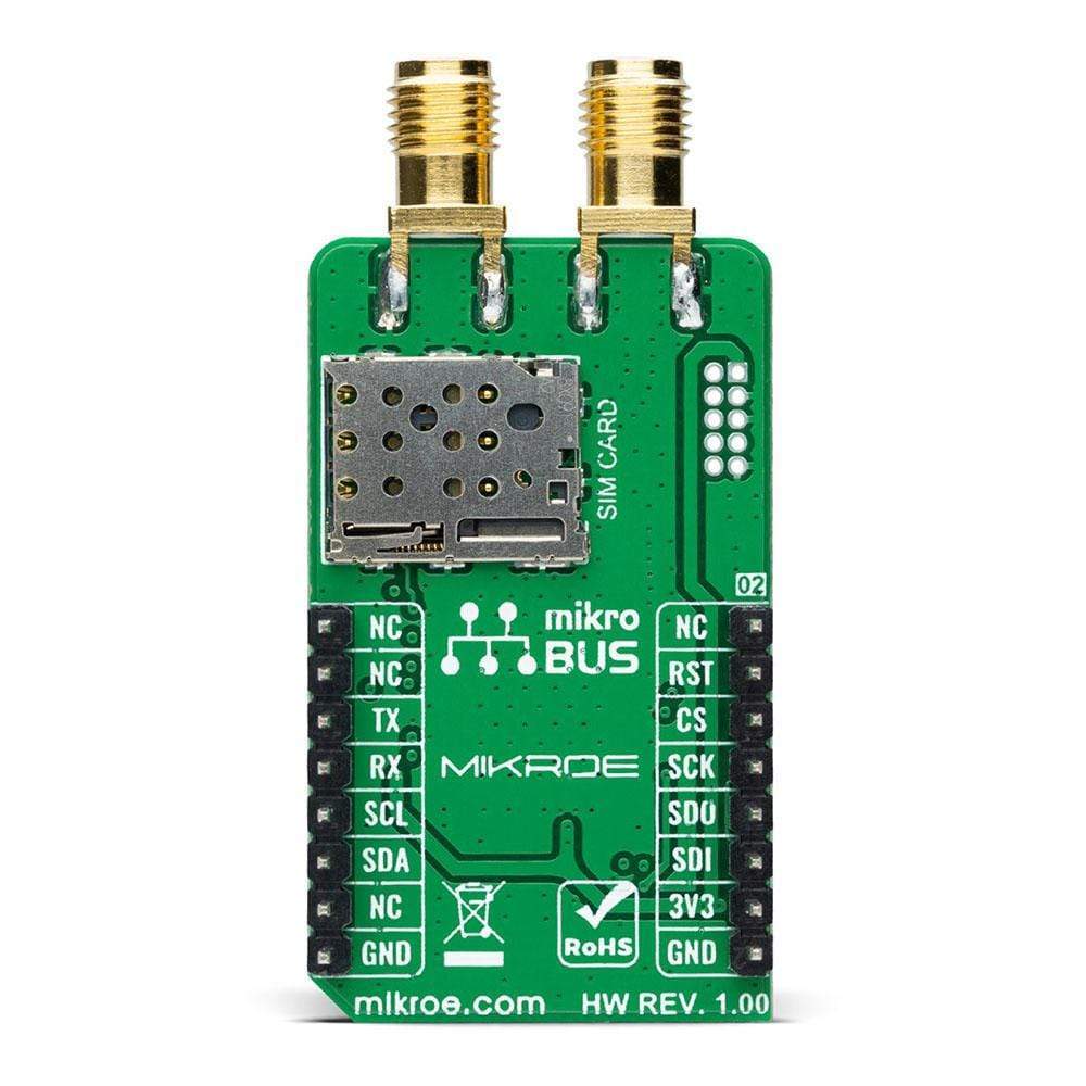
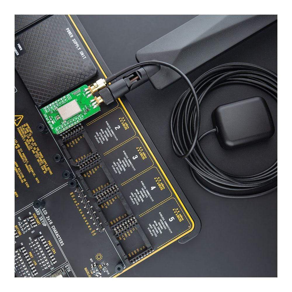
The LTE modem integrates a flexible transceiver that supports a frequency range of 700 to 2200 MHz. Also, it possesses two SMA antenna connectors with an impedance of 50Ω, labelled as GPS and LTE, used for connecting the appropriate antenna that MikroE has in its offer. Besides those SMA connectors, this Click board™ also has a nano-SIM card slot that provides multiple connections and interface options.
The LTE IoT 4 Click Board™ is designed to be operated only with a 3.3V logic voltage level. A proper logic voltage level conversion should be performed before the Click board™ is used with MCUs with different logic levels. However, the Click board™ comes equipped with a library containing functions and an example code that can be used as a reference for further development.
SPECIFICATIONS
Type | LTE IoT,GPS+GNSS |
Applications | Can be used for applications such as logistics and asset tracking, predictive maintenance, industrial, smart agriculture, and many more. |
On-board modules | nRF9160 - highly-integrated System-in-The package (SiP) with integrated ARM® Cortex®-M33 processor, multimode LTE-M/ NB-IoT modem, RF front end (RFFE), GPS, and power management from Nordic Semiconductor. |
Key Features | Low power consumption, fully integrated SiP, multimode LTE-M/NB-IoT modem with integrated RFFE, assisted GPS, certified for global operation, and more. |
Interface | I2C,UART,SPI |
Compatibility | mikroBUS |
Click board size | M (42.9 x 25.4 mm) |
Input Voltage | 3.3V |
PINOUT DIAGRAM
This table shows how the LTE IoT 4 Click Board™ pinout corresponds to the pinout on the mikroBUS™ socket (the latter shown in the two middle columns).
Notes | Pin | | Pin | Notes | |||
---|---|---|---|---|---|---|---|
NC | 1 | AN | PWM | 16 | NC | ||
Reset | RST | 2 | RST | INT | 15 | NC | |
SPI Chip Select | CS | 3 | CS | RX | 14 | TX | UART TX |
SPI Clock | SCK | 4 | SCK | TX | 13 | RX | UART RX |
SPI Data OUT | SDO | 5 | MISO | SCL | 12 | SCL | I2C Clock |
SPI Data IN | SDI | 6 | MOSI | SDA | 11 | SDA | I2C Data |
Power Supply | 3.3V | 7 | 3.3V | 5V | 10 | NC | |
Ground | GND | 8 | GND | GND | 9 | GND | Ground |
ONBOARD SETTINGS AND INDICATORS
Label | Name | Default | Description |
---|---|---|---|
LD1 | PWR | - | Power LED Indicator |
J1 | SWD | Unpopulated | Serial Wire Debug (SWD) Interface |
LTE IOT 4 CLICK ELECTRICAL SPECIFICATIONS
Description | Min | Typ | Max | Unit |
---|---|---|---|---|
Supply Voltage | - | 3.3 | - | V |
Operating Frequency Range | 700 | - | 2200 | MHz |
Operating Temperature Range | -40 | +25 | +85 | °C |
Software Support
We provide a library for the LTE IoT 4 Click Board™ and a demo application (example), developed using MikroElektronika compilers. The demo can run on all the main MikroElektronika development boards.
The package can be downloaded/installed directly from NECTO Studio The package Manager (recommended), downloaded from our LibStock™ or found on the mikroE Github account.
Library Description
This library contains an API for the LTE IoT 4 Click Board™ driver.
Key Functions
void lteiot4_cfg_setup ( lteiot4_cfg_t *cfg );
- Config Object Initialization function.LTEIOT4_RETVAL lteiot4_init ( lteiot4_t *ctx, lteiot4_cfg_t *cfg );
- Initialization function.void lteiot4_default_cfg ( lteiot4_t *ctx );
- Click the Default Configuration function.
Example Description
This example reads and processes data from the LTE IoT 4 Click Board™.
void application_task ( void ) { if ( app_connection_status == WAIT_FOR_CONNECTION ) { //CEREG log_info( &logger, " Check connection " ); lteiot4_send_cmd( <eiot4, LTEIOT4_CMD_CHECK_CONNECTION ); app_error_flag = lteiot4_rsp_check(); lteiot4_error_check( app_error_flag ); Delay_ms( 500 ); //CEREG log_info( &logger, " Check network status " ); lteiot4_send_cmd( <eiot4, LTEIOT4_CMD_CHECK_REGISTARTION ); app_error_flag = lteiot4_rsp_check(); lteiot4_error_check( app_error_flag ); Delay_ms( 500 ); //CEREG log_info( &logger, " Check signal quality " ); lteiot4_send_cmd( <eiot4, LTEIOT4_CMD_SIGNAL_QUALITY ); app_error_flag = lteiot4_rsp_check(); lteiot4_error_check( app_error_flag ); log_printf( &logger, "-------------------------------rn" ); Delay_ms( 5000 ); } else { log_info( &logger, "CONNECTED TO NETWORKrn" ); log_printf( &logger, "-------------------------------rn" ); //CCLK log_info( &logger, " Set Time " ); lteiot4_send_cmd( <eiot4, LTEIOT4_CMD_SET_DUMMY_CLOCK ); app_error_flag = lteiot4_rsp_check(); lteiot4_error_check( app_error_flag ); log_printf( &logger, "-------------------------------rn" ); Delay_ms( 3000 ); for(;;) { //XTEMP log_info( &logger, " Check Temperature " ); lteiot4_send_cmd( <eiot4, LTEIOT4_CMD_CHECK_TEMPERATURE ); app_error_flag = lteiot4_rsp_check(); lteiot4_error_check( app_error_flag ); Delay_ms( 500 ); //CCLK log_info( &logger, " Check Time " ); lteiot4_send_cmd( <eiot4, LTEIOT4_CMD_CHECK_CLOCK ); app_error_flag = lteiot4_rsp_check(); lteiot4_error_check( app_error_flag ); log_printf( &logger, "-------------------------------rn" ); Delay_ms( 5000 ); } } }
The complete application code and ready-to-use projects can be installed directly from NECTO Studio The package Manager (recommended), downloaded from our LibStock™ or found on the mikroE Github account.
Other mikroE Libraries used in the example:
- MikroSDK.Board
- MikroSDK.Log
- Click.LTEIoT4
Additional Notes and Information
Depending on the development board you are using, you may need a USB UART Click Board™, USB UART 2 Click Board™ or RS232 Click Board™ to connect to your PC, for development systems with no UART to USB interface available on the board. The terminal available in all MikroElektronika compilers, or any other terminal application of your choice, can be used to read the message.
MIKROSDK
The LTE IoT 4 Click Board™ ™ is supported with mikroSDK - MikroElektronika Software Development Kit. To ensure proper operation of mikroSDK compliant Click board™ demo applications, mikroSDK should be downloaded from the LibStock and installed for the compiler you are using.
LTE IoT 4 Click Board
Frequently Asked Questions
Have a Question?
Be the first to ask a question about this.