


Mikroelektronika d.o.o.
NB IoT 5 Click Board™
NB IoT 5 Click Board™
SKU: MIKROE-4472
Couldn't load pickup availability


Overview
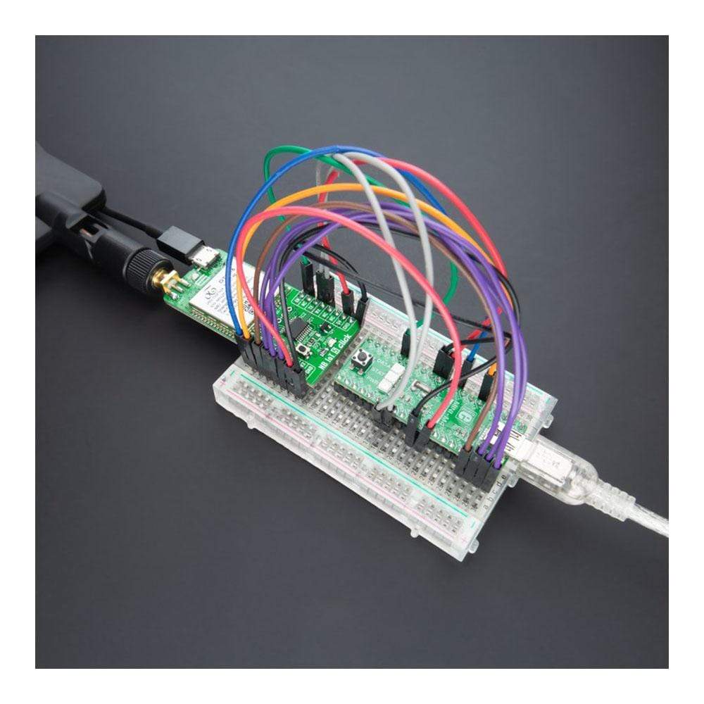
The NB IoT 5 Click Board™ is a compact add-on board suitable as narrow-band Internet of Things universal wireless communication solution. This board features the OT01-5, a high-performance NB-IoT module with ultra-low power consumption allowing battery life of about ten years from Notion. It supports a broad range of frequency bands almost worldwide. It provides serial interfaces, UART and SPI, with protocol stacks such as UDP/TCP, CoAP, LWM2M, and others. It offers an alternative to similar Low Power Wide Area Network (LPWAN) solutions. This Click Board™ is suitable for many IoT applications such as intelligent gas/water meters, information collection, security monitoring, smart city/home, and other applications.
The NB IoT 5 Click Board™ is supported by a mikroSDK compliant library, which includes functions that simplify software development. This Click Board™ comes as a thoroughly tested product, ready to be used on a system equipped with the mikroBUS™ socket.
Downloads
How Does The NB IoT 5 Click Board™ Work?
The NB IoT 5 Click Board™ as its foundation uses the OT01-5, a high-performance narrow-band Internet of Things universal wireless communication module with meagre power consumption allowing battery life of about ten years from Notion. It supports a broad range of frequency bands worldwide, such as 1 / 2 / 3 / 5 / 8 / 19 / 20 of 3GPP R13 (NB1) and R14 (NB2). It also provides several interfaces, UART, SPI, and protocol stacks such as UDP/TCP, CoAP, LWM2M, and others. In addition to motor driver inside-design, these protocols allow data and SMS transfer using the NB technology. This module is perfect for building IoT applications and smart gas and water meters without an external microcontroller unit.
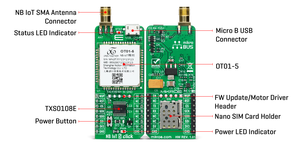
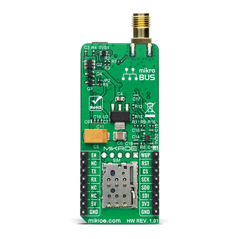
There are two ways to turn on this Click board™, through EN pin on the mikroBUS™ socket or by pressing the PWRKEY button for a period longer than 3 seconds. The onboard push-button labelled PWRKEY routed to the PWM pin on the mikroBUS™ socket represents the Ignition (Power-On) button. This feature is shown by the yellow diode labelled as STAT used to indicate the device's Operational Status.
The NB IoT 5 Click Board™ communicates with MCU using the UART interface as its default communication protocol with the option for the users to use another interface such as SPI if they want to configure the module and write the library by themselves. It supports automatic baud rate detection, operates at 115200 bps by default configuration, and is used for data transmission and exchanging AT commands with the host MCU. Also, it has an additional header used for firmware upgrades, software debugging, log capturing, or even as a motor drive.
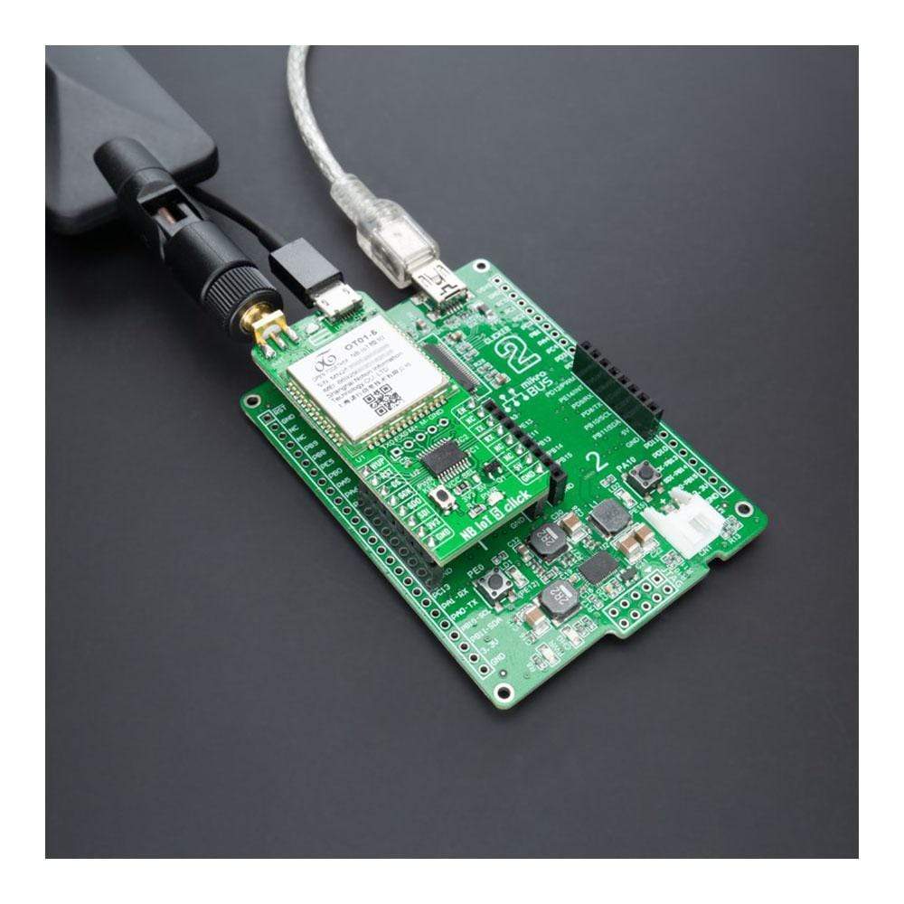
In addition to these features, the OT01-5 also uses several GPIO pins connected to the mikroBUS™ socket. The WUP pin routed on the AN pin of the mikroBUS™ represents the Wake-up function used for waking up the device, while the RST pin on the mikroBUS™ socket can perform the Hardware Reset function by putting this pin in a logic low state. This Click board™ also has the micro USB connector allowing the module to be powered and configured by a personal computer.
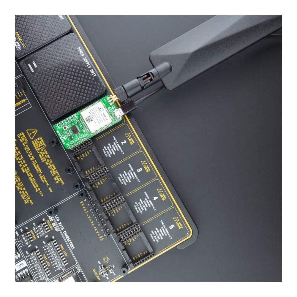
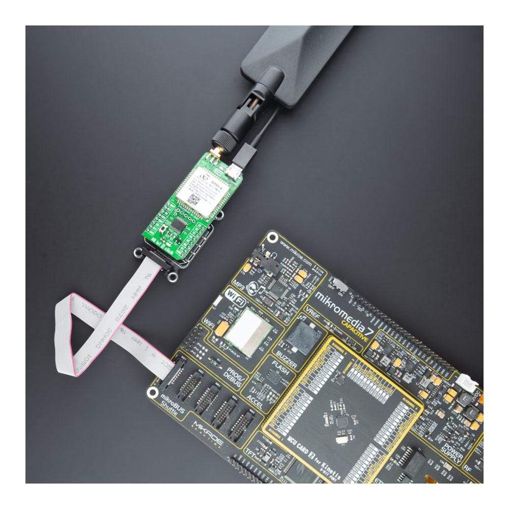
The NB IoT 5 Click Board™ possesses the SMA antenna connector with an impedance of 50Ω. This Click board™ can use it to connect the appropriate antenna, such as the LTE Flat Rotational Antenna that MikroE has in its offer. Besides the SMA connector, it also has a Nano-SIM card slot that provides multiple connections and interface options.
The NB IoT 5 Click Board™ can operate with both 3.3V, and 5V MCUs set via jumper labelled as VCC SEL with a proper logic voltage level conversion performed by the appropriate voltage level translator TXS0108E. This way, it is allowed for both 3.3V and 5V capable MCUs to use communication lines properly. However, the Click board™ comes equipped with a library containing functions and an example code that can be used, as a reference, for further development.
SPECIFICATIONS
| Type | LTE IoT |
| Applications | Can be used for a wide range of IoT applications such as smart gas/water meters, information collection, security monitoring, smart city/home, and other applications |
| On-board modules | OT01-5 - high-performance narrow-band Internet of Things universal wireless communication module with meagre power consumption allowing battery life of about ten years from Notion |
| Key Features | Ultra-low power consumption, high performance, a broad range of frequency bands, motor driver inside-design, global operation certification, and more. |
| Interface | SPI, UART, USB |
| Compatibility | mikroBUS |
| Click board size | L (57.15 x 25.4 mm) |
| Input Voltage | 3.3V or 5V |
PINOUT DIAGRAM
This table shows how the NB IoT 5 Click Board™ pinout corresponds to the pinout on the mikroBUS™ socket (the latter shown in the two middle columns).
| Notes | Pin | Pin | Notes | ||||
|---|---|---|---|---|---|---|---|
| Wake-Up | WUP | 1 | AN | PWM | 16 | EN | Power-On Control |
| Reset | RST | 2 | RST | INT | 15 | NC | |
| SPI Chip Select | CS | 3 | CS | RX | 14 | TX | UART TX |
| SPI Clock | SCK | 4 | SCK | TX | 13 | RX | UART RX |
| SPI Data OUT | SDO | 5 | MISO | SCL | 12 | NC | |
| SPI Data IN | SDI | 6 | MOSI | SDA | 11 | NC | |
| Power Supply | 3.3V | 7 | 3.3V | 5V | 10 | 5V | Power Supply |
| Ground | GND | 8 | GND | GND | 9 | GND | Ground |
ONBOARD SETTINGS AND INDICATORS
| Label | Name | Default | Description |
|---|---|---|---|
| LD1 | PWR | - | Power LED Indicator |
| LD2 | STAT | - | Status LED Indicator |
| JP1 | VCC SEL | Left | Logic Level Voltage Selection 3V3/5V: Left position 3V3, Right position 5V |
| CN1 | - | Unpopulated | FW Update / Motor Driver Header |
| T1 | PWRKEY | - | Power Button |
NB IOT 5 CLICK ELECTRICAL SPECIFICATIONS
| Description | Min | Typ | Max | Unit |
|---|---|---|---|---|
| Supply Voltage | 3.3 | - | 5 | V |
| Operating Frequency Range | 800 | - | 1800 | MHz |
| Operating Temperature Range | -20 | +25 | +60 | °C |
| General Information | |
|---|---|
Part Number (SKU) |
MIKROE-4472
|
Manufacturer |
|
| Physical and Mechanical | |
Weight |
0.02 kg
|
| Other | |
EAN |
8606027381935
|
Frequently Asked Questions
Have a Question?
Be the first to ask a question about this.