

Mikroelektronika d.o.o.
Angle 5 Click Board™ Bundle
Angle 5 Click Board™ Bundle
SKU: MIKROE-4368
Couldn't load pickup availability
Overview
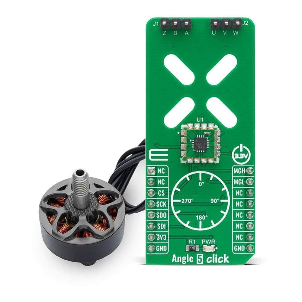
The Angle 5 Click Board™ Bundle - Add an angle sensor in BLDC Motor for accurate control and high-efficiency commutation of the motor and rotary position information. This bundle allows users to combine BLDC Motor a 12-bit digital contactless angle sensor with ABZ and UVW incremental outputs from Monolithic Power Systems
Downloads
How Does The Angle 5 Click Board™ Work?
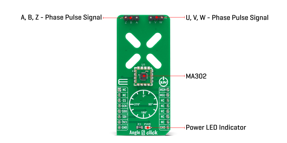
The Angle 5 Click Board™ is based on the MA302, a 12-bit digital contactless angle sensor with ABZ and UVW incremental outputs from Monolithic Power Systems. This Click board™ can detect the absolute rotor position of a Brushless motor in real-time, even without a target magnet, by measuring the fringe field of the rotor. The sensor must be positioned at the correct place (in this case below the rotor) to get the maximum value of the rotor magnetic field without being disturbed by other fields. The rotor magnetic field is then measured, and an adequate position was determined from that information. It uses the SPI serial interface for digital angle readout and configuration, alongside with programmable magnetic field strength detection function for diagnostic checks.
The magnetic field is detected with integrated Hall devices located in the center of the package. The angle is measured using the Spinaxis™ method, based on phase detection and generates a sinusoidal signal with a phase that represents the angle of the magnetic field. The angle is then obtained by a time-to-digital converter, which measures the time between the zero-crossing of the sinusoidal signal and the edge of a constant waveform. The time-to-digital represents an output from the front-end to the digital conditioning block. This output delivers a digital number proportional to the angle of the magnetic field at the rate of 1MHz in a straightforward and open-loop manner.
The Angle 5 Click communicates with MCU using the standard SPI serial interface for angle reading and register programming, which supports SPI Mode 0 and 3 and operates at clock rates up to 25 MHz. It also has the magnetic flags used for indication when the magnetic field at the sensor position is out of range, defined by the lower and upper magnetic field thresholds, routed on the PWM and INT pin of the mikroBUS™ socket labelled as MGH and MGL.
The Angle 5 Click Board™ possesses an incremental encoder and block commutation function that uses three output pins each: ABZ and UVW. The ABZ output emulates a 10-bit incremental encoder (such as an optical encoder) providing logic pulses in quadrature, while the UVW output emulates the three Hall switches usually used for the block commutation of a three-phase electric motor. The ABZ and UVW pins of the MA302 are routed on two standard 2.54 mm (0.1 inches) pitch 1x3 header, mounted on the Angle 5 Click, so it can be easily accessed by an external application.
The Angle 5 Click Board™ is designed to be operated only with a 3.3V logic voltage level. A proper logic voltage level conversion should be performed before the Click board™ is used with MCUs with different logic levels. However, the Click board™ comes equipped with a library that contains easy to use functions and an example code that can be used as a reference for further development.
SPECIFICATIONS
| Type | Magnetic |
| Applications | The Angle 5 Click Board™ can be used for various applications such as detecting the absolute rotor position of a brushless motor in real-time, even without a target magnet, by measuring the fringe field of the rotor. |
| On-board modules | The Angle 5 Click Board™ is based on the MA302, a 12-bit digital contactless angle sensor with ABZ and UVW incremental outputs from Monolithic Power Systems. |
| Key Features | Fast data acquisition, magnetic field strength detection, contactless sensing for long life, supported both end-of-shaft and off-axis, and many more. |
| Interface | SPI |
| Compatibility | mikroBUS |
| Click board size | L (57.15 x 25.4 mm) |
| Input Voltage | 3.3V |
PINOUT DIAGRAM
This table shows how the pinout of the Angle 5 Click Board™ corresponds to the pinout on the mikroBUS™ socket (the latter shown in the two middle columns).
| Notes | Pin | Pin | Notes | ||||
|---|---|---|---|---|---|---|---|
| NC | 1 | AN | PWM | 16 | MGH |
Magnetic Field |
|
| NC | 2 | RST | INT | 15 | MGL |
Magnetic Field |
|
| SPI Chip Select | CS | 3 | CS | RX | 14 | NC | |
| SPI Clock | SCK | 4 | SCK | TX | 13 | NC | |
| SPI Data OUT | SDO | 5 | MISO | SCL | 12 | NC | |
| SPI Data IN | SDI | 6 | MOSI | SDA | 11 | NC | |
| Power Supply | 3.3V | 7 | 3.3V | 5V | 10 | NC | |
| Ground | GND | 8 | GND | GND | 9 | GND | Ground |
ONBOARD SETTINGS AND INDICATORS
| Label | Name | Default | Description |
|---|---|---|---|
| LD1 | PWR | - | Power LED Indicator |
| J1 | M1x3 | - | A, B, Z incremental encoder outputs |
| J2 | M1x3 | - | U, V, W block commutation outputs |
ANGLE 5 CLICK ELECTRICAL SPECIFICATIONS
| Description | Min | Typ | Max | Unit |
|---|---|---|---|---|
| Supply Voltage | -0.5 | 3.3 | +4.6 | V |
| Applied Magnetic Filed | 30 | 60 | - | mT |
| Magnetic Field Detection Accuracy | - | 5 | - | mT |
| Effective resolution | 11 | 11.8 | 12.8 | bit |
| Operating Temperature Range | -40 | - | +125 | °C |
| General Information | |
|---|---|
Part Number (SKU) |
MIKROE-4368
|
Manufacturer |
|
| Physical and Mechanical | |
Weight |
0.02 kg
|
| Other | |
EAN |
5055383600434
|
Frequently Asked Questions
Have a Question?
Be the first to ask a question about this.