


Mikroelektronika d.o.o.
Buck & Boost Click Board™
Buck & Boost Click Board™
SKU: MIKROE-4354
Couldn't load pickup availability
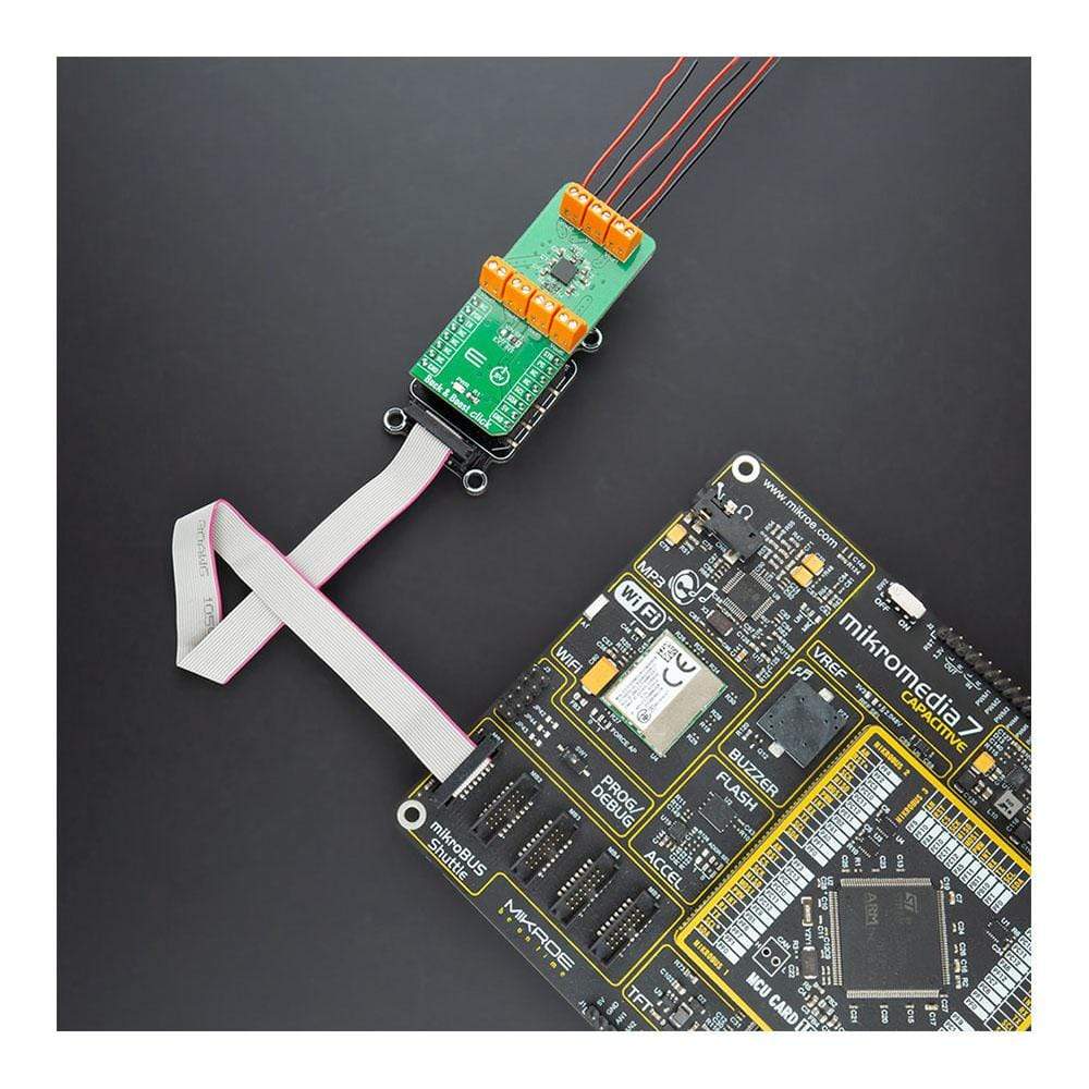
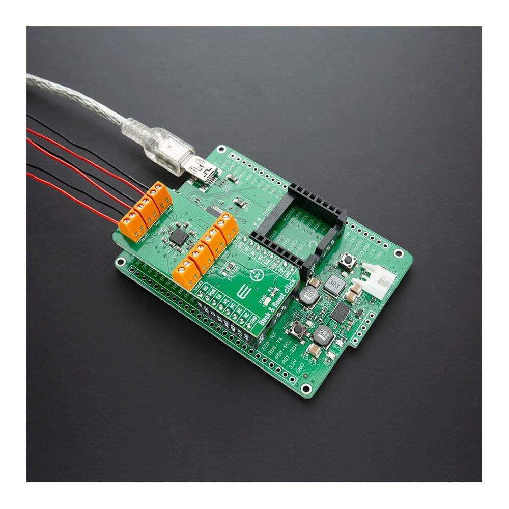
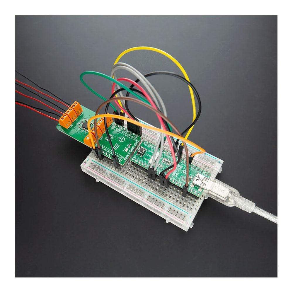
Overview
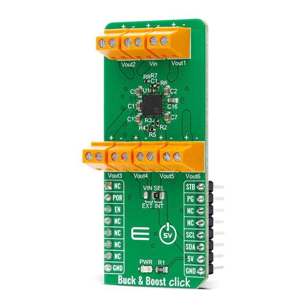
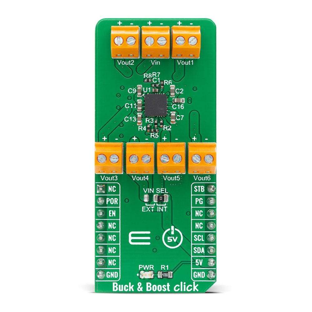
The Buck & Boost Click Board™ is a compact add-on board that contains a configurable power management device. This board features the MIC7401, a highly-integrated power-management IC featuring five synchronous buck regulators, one boost regulator, and a high-speed I2C interface with an internal EEPROM memory from Microchip. The MIC7401 offers two distinct modes of operation (Standby and Normal) and includes a global enable pin to shut down the device for additional power savings. Some features of this Click Board™ like an energy-optimized solution, flexibility, and high-performance make it an excellent choice for portable handheld and infotainment applications.
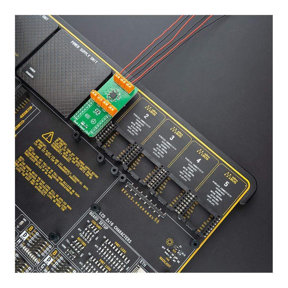
The Buck & Boost Click is supported by a mikroSDK compliant library, which includes functions that simplify software development. This Click Board™ comes as a fully tested product, ready to be used on a system equipped with the mikroBUS™ socket.
Downloads
How Does The Buck & Boost Click Board™ Work?
The Buck & Boost Click Board™ is based on the MIC7401, a powerful highly-integrated configurable power management (PMIC) featuring buck and boost regulators and a high-speed I2C interface with an internal EEPROM memory and micro-power shutdown function from Microchip. The Buck & Boost Click Board™ has five 3A synchronous buck regulators with high-speed adaptive on-time control and one boost regulator that provides a flash-memory programming supply that delivers up to 200mA of output current. The boost is equipped with an output disconnect switch that opens if a short-to-ground fault is detected.

The MIC7401 offers two distinct modes of operation Standby and Normal mode intended to provide an energy-optimized solution suitable for portable handheld and infotainment applications. In Normal mode, the programmable switching converters can be configured to support a variety of Start-up sequencing, timing, soft-start ramp, output voltage levels, current limit levels, and output discharge for each channel. In Standby mode this PMIC can be configured in a low-power state by either disabling an output or by changing the output voltage to a lower level. Independent exit from Standby mode can be achieved either by I2C communication or the STB pin of the mikroBUS™ socket.
The Buck & Boost Click Board™ communicates with MCU using the standard I2C 2-Wire interface with a frequency up to 100kHz in the Standard, up to 400 kHz in the Fast, and up to 3.4MHz in the High-Speed mode. This Click board™ also contains additional functionalities routed to the CS, AN, PWM, and INT pins on the mikroBUS™ socket. CS pin labeled as EN represents an enable pin that shuts down the device for additional power savings. PWM pin labeled as STB represents Standby Reset function that allows the total power consumption to be reduced by either lowering a supply voltage or turning it off. In addition to these functions, this Click board™ has Power-On Reset that goes high after the POR delay time elapses, as well as Global Power-Good output that is pulled high when all the regulators power-good flags are high.
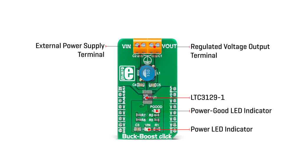
The Buck & Boost Click Board™ is designed to be operated with 5V logic voltage level from mikroBUS™ or a voltage from an external input terminal in the range from 2.4 to 5.5V that can be selected via the VIN SEL jumper. In this way, whether using a logic voltage level from mikroBUS™ socket or an external voltage supply, this allows for both 3.3V and 5V capable MCUs to use the I2C communication lines properly.
SPECIFICATIONS
| Type | Buck-Boost |
| Applications | Can be used for portable handheld and infotainment applications. |
| On-board modules | The Buck & Boost Click Board™ is based on the MIC7401, a powerful highly-integrated configurable power management (PMIC) featuring buck and boost regulators and a high-speed I2C interface with an internal EEPROM memory and micro-power shutdown function from Microchip. |
| Key Features | High-density five buck channels, one independent boost channel, 93% peak efficiency, fast transient response, short-to-ground fault detection, and more. |
| Interface | I2C |
| Compatibility | mikroBUS |
| Click board size | L (57.15 x 25.4 mm) |
| Input Voltage | 5V,External |
Pinout Diagram
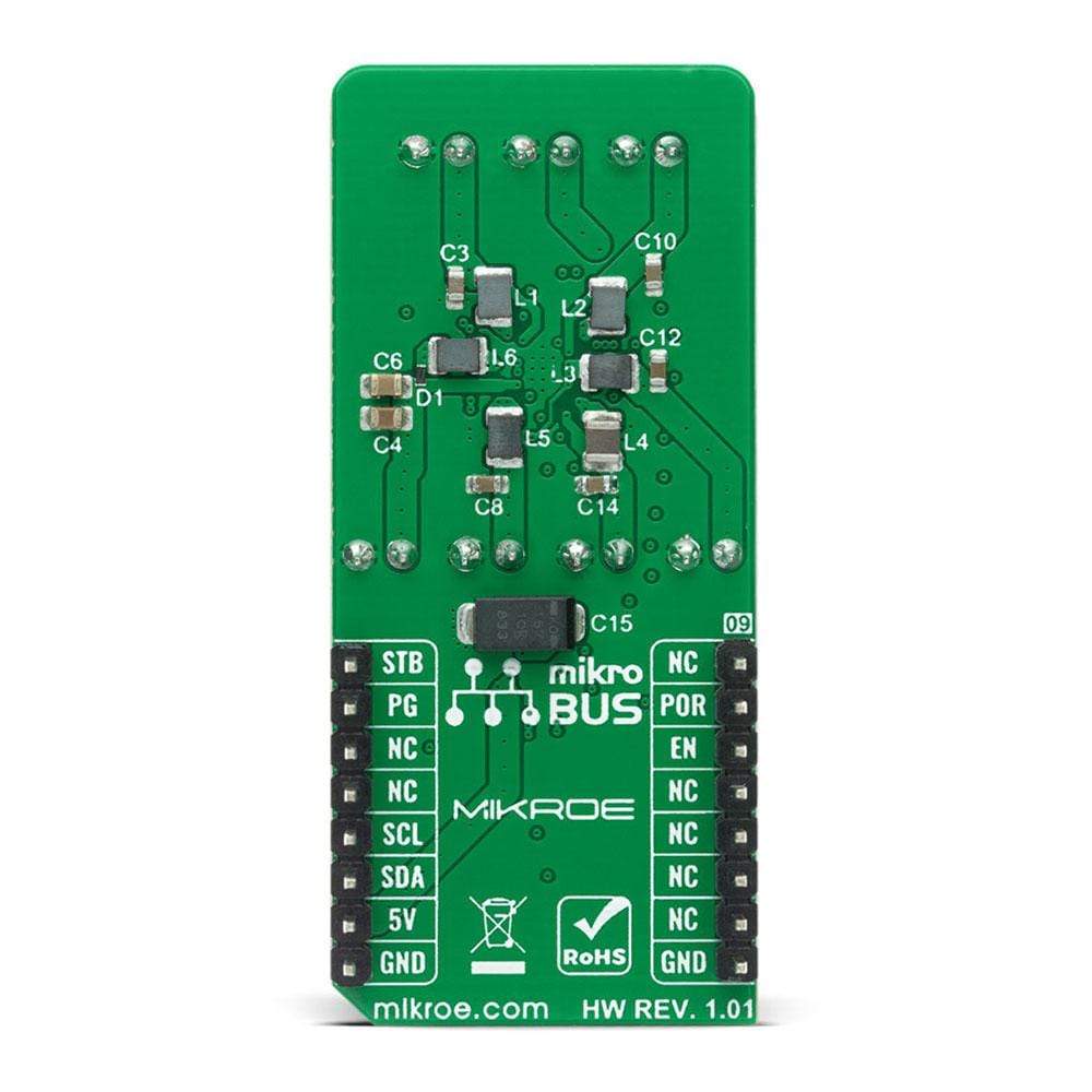
This table shows how the pinout of the Buck & Boost Click Board™ corresponds to the pinout on the mikroBUS™ socket (the latter shown in the two middle columns).
| Notes | Pin |
 |
Pin | Notes | |||
|---|---|---|---|---|---|---|---|
| NC | 1 | AN | PWM | 16 | STB | Stanby | |
| Power-ON Reset | POR | 2 | RST | INT | 15 | PG | Global Power Good |
| Enable | EN | 3 | CS | RX | 14 | NC | |
| NC | 4 | SCK | TX | 13 | NC | ||
| NC | 5 | MISO | SCL | 12 | SCL | I2C Clock | |
| NC | 6 | MOSI | SDA | 11 | SDA | I2C Data | |
| NC | 7 | 3.3V | 5V | 10 | 5V | Power Supply | |
| Ground | GND | 8 | GND | GND | 9 | GND | Ground |
ONBOARD SETTINGS AND INDICATORS
| Label | Name | Default | Description |
|---|---|---|---|
| LD1 | PWR | - | Power LED Indicator |
| JP1 | VIN SEL | Right | Power Supply Voltage Selection EXT/INT: Left position External, Right position 5V |
BUCK & BOOST CLICK ELECTRICAL SPECIFICATIONS
| Description | Min | Typ | Max | Unit |
|---|---|---|---|---|
| Supply Voltage (INT) | - | 5 | - | V |
| Supply Voltage VIN (EXT) | -0.3 | - | 6 | V |
| Maximum Buck Output Voltage (VOUT[1-5]) | -0.3 | - | 6 | V |
| Maximum Boost Output Voltage (VOUT6) | -0.3 | - | 20 | V |
| Maximum Buck Output Current | - | - | 3 | A |
| Maximum Boost Output Current | - | - | 200 | mA |
| Operating Temperature Range | -40 | - | +125 | °C |
| General Information | |
|---|---|
Part Number (SKU) |
MIKROE-4354
|
Manufacturer |
|
| Physical and Mechanical | |
Weight |
0.024 kg
|
| Other | |
EAN |
8606027380921
|