Overview
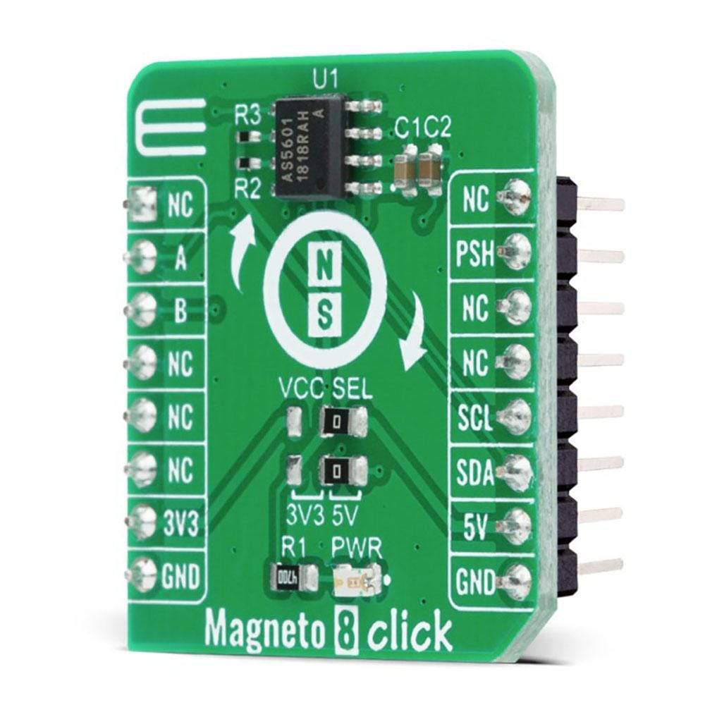
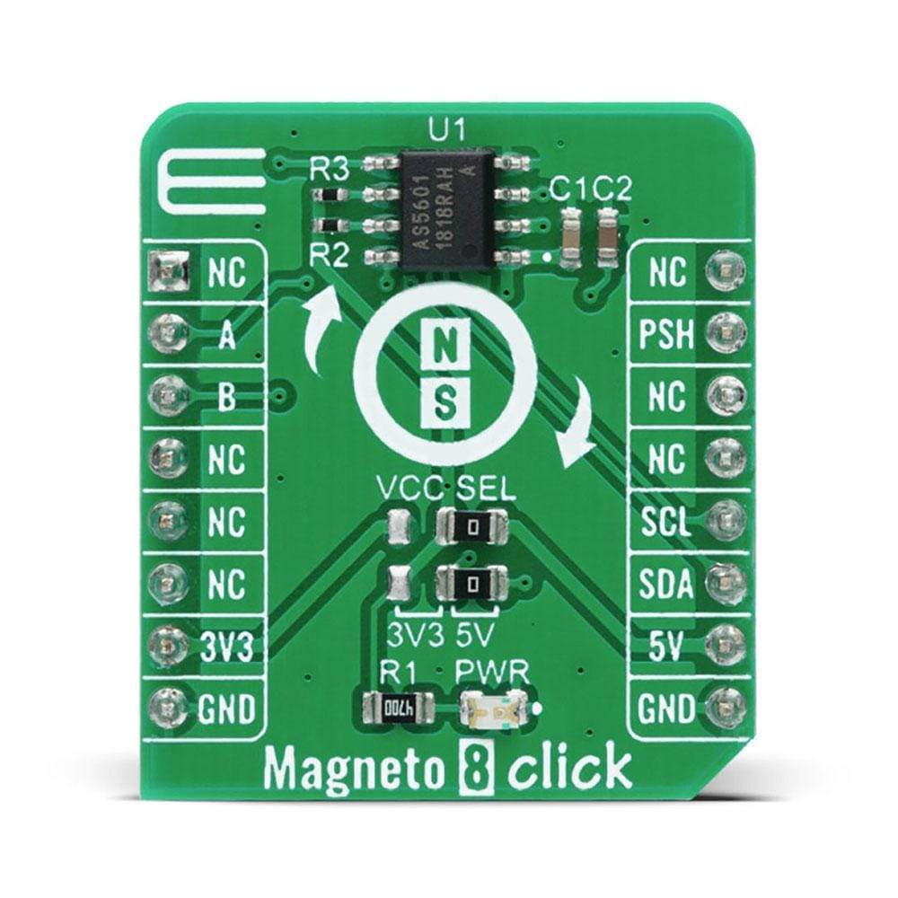
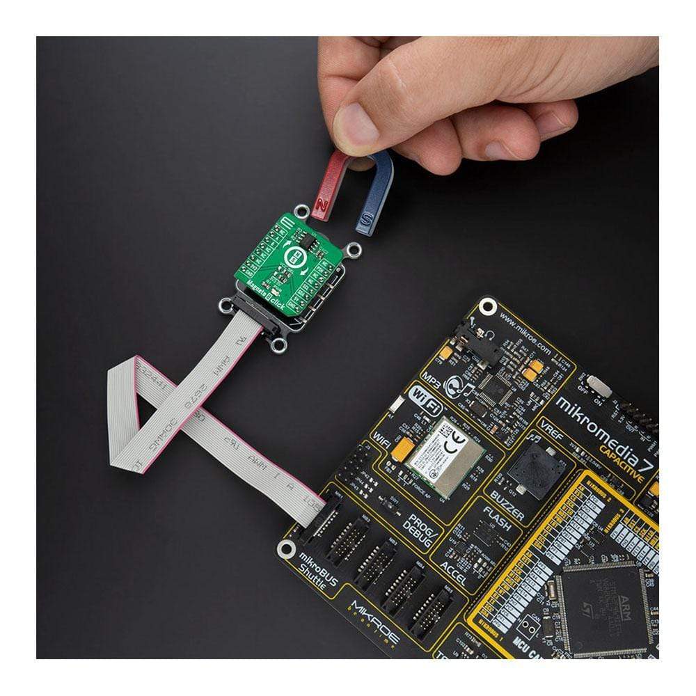
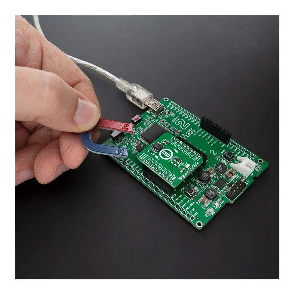
The Magneto 8 Click Board™ is a compact add-on board that contains an easy-to-program magnetic rotary position sensor with incremental quadrature (A/B) and 12-bit digital outputs. This board features the AS5601, 12-bit programmable contactless encoder IC from AMS-AG. This Click Board™ is based on a planar Hall sensor technology, supports an industry-standard I2C interface, and it measures the orthogonal component of the flux density (Bz) from an external magnet. It also provides a smart low-power mode that automatically reduces power consumption. Magneto 8 Click has many features that make it attractive for various applications such as angular position measurement solutions, encoder replacement, contactless magnetic position sensors, and more.
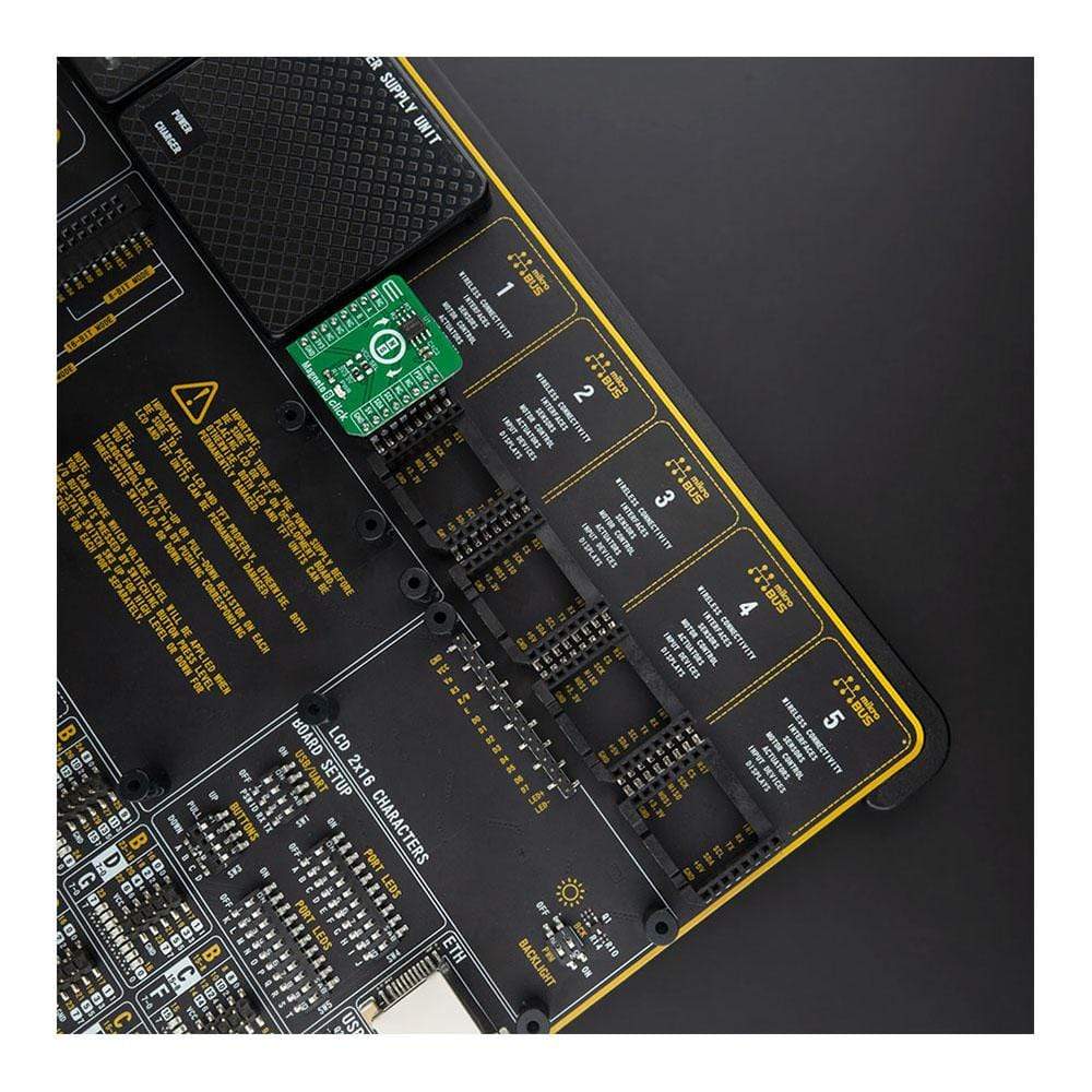
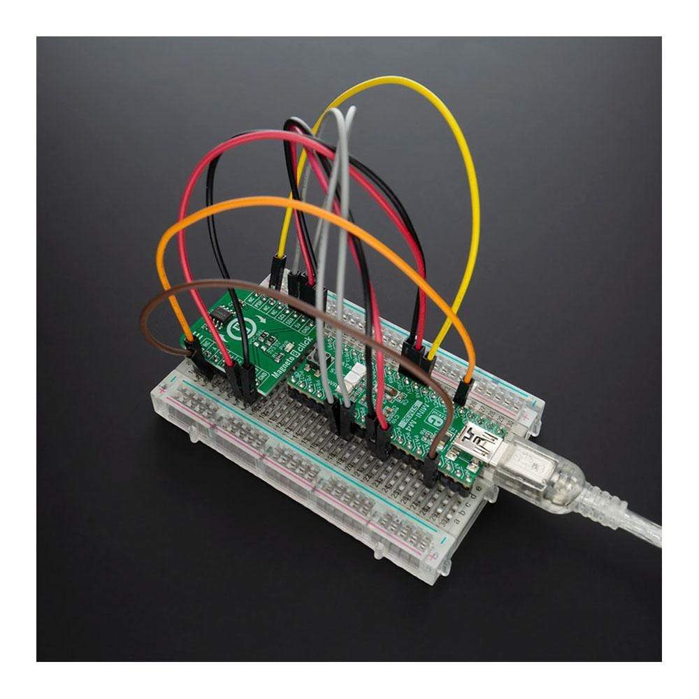
The Magneto 8 Click Board™ is supported by a mikroSDK compliant library, which includes functions that simplify software development. This Click Board™ comes as a fully tested product, ready to be used on a system equipped with the mikroBUS™ socket.
Downloads
How Does The Magneto 8 Click Board™ Work?
The Magneto 8 Click Board™ is based on the AS5601, 12-bit programmable contactless encoder IC from AMS-AG. The AS5601 is a Hall-based rotary magnetic position encoder that converts the magnetic field component vertical to the surface of the chip into a voltage, which is used to produce incremental A/B outputs and absolute position indication. The analog signals from the Hall sensor are first amplified and filtered (before being converted by the ADC into binary data), and then are processed by the CORDIC block to compute the angle and magnitude of the magnetic field vector. The angle values provided by the CORDIC algorithm are used by the internal logic to generate the incremental quadrature signals A and B.
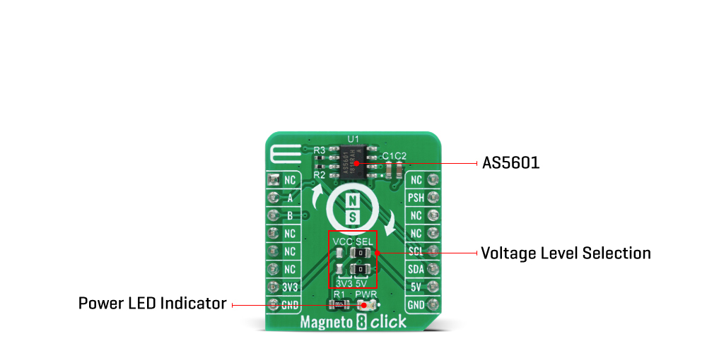
Additionally, the AS5601 implements a pushbutton detection function that indicates sudden airgap changes between the AS5601 and magnet, and drives the PUSH output pin high when the AS5601 detects a fast increase of the magnetic field and vice versa. The AS5601 communicates with MCU using the standard I2C 2-Wire interface with the maximum SCL frequency of 1 MHz. I2C communication interface supports several different modes. In addition to the modes such as Standard, Fast, and Fast-Plus mode there are 3 additional modes like Random/Sequential read, Byte/Page write, and Automatic increment relating to the ANGLE register.
The AS5601 can be powered from a 5V supply using the on-chip LDO regulator, or it can be powered directly from a 3.3V supply. The selection can be done by positioning SMD jumpers labelled as VCC SEL to an appropriate position. In this case, there are two voltage selection jumpers because the power pins of the AS5601 require a different configuration in the case of 3.3V and 5V power supply. In 5V operation, the second power pin needs to be connected to the ground via a decoupling capacitor C2. Otherwise, in 3.3V operation, the two pins must be tied together. Note that all the jumpers must be placed to the same side, or else the Click board™ may become unresponsive.
The Magneto 8 Click Board™ uses the I2C communication interface with both 3.3V and 5V. The onboard SMD jumper labelled as VCC SEL allows voltage selection for interfacing with both 3.3V and 5V MCUs. More information about the AS5601's functionality, electrical specifications, and typical performance can be found in the attached datasheet. However, the Click board™ comes equipped with a library that contains easy to use functions and a usage example that may be used as a reference for the development.
SPECIFICATIONS
| Type | Magnetic |
| Applications | The Magneto 8 Click Board™ be used for a angular position measurement solutions, encoder replacement, contactless magnetic position sensors, and more. |
| On-board modules | Magneto 8 Click is based on the AS5601, 12-bit programmable contactless encoder IC from AMS-AG. |
| Key Features | High reliability and durability, low power consumption, simple programming, and more. |
| Interface | GPIO,I2C |
| Compatibility | mikroBUS |
| Click board size | S (28.6 x 25.4 mm) |
| Input Voltage | 3.3V or 5V |
PINOUT DIAGRAM
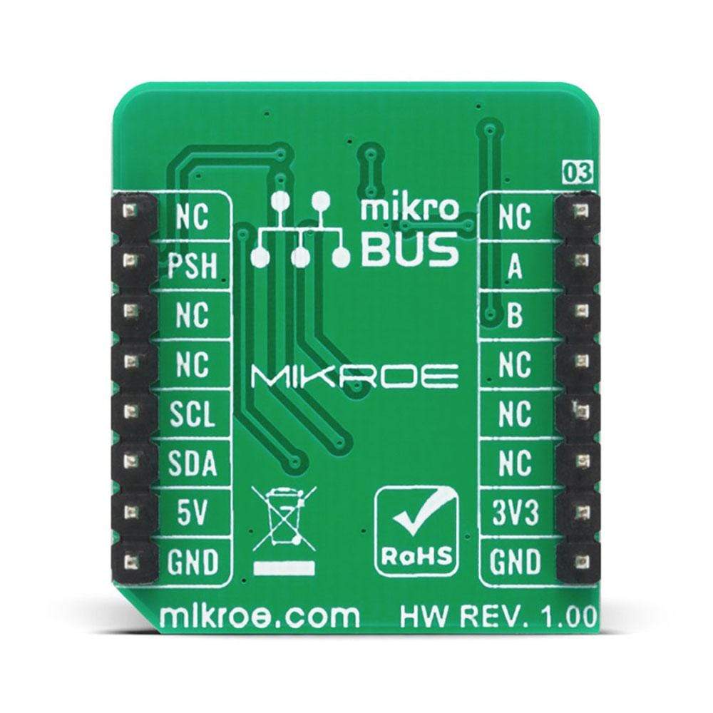
This table shows how the pinout of the Magneto 8 Click Board™ corresponds to the pinout on the mikroBUS™ socket (the latter shown in the two middle columns).
| Notes | Pin |  |
Pin | Notes | |||
|---|---|---|---|---|---|---|---|
| NC | 1 | AN | PWM | 16 | NC | ||
| Incremental signal A | A | 2 | RST | INT | 15 | PSH | Pushbutton output |
| Incremental signal B | B | 3 | CS | RX | 14 | NC | |
| NC | 4 | SCK | TX | 13 | NC | ||
| NC | 5 | MISO | SCL | 12 | SCL | I2C Clock | |
| NC | 6 | MOSI | SDA | 11 | SDA | I2C Data | |
| Power Supply | 3.3V | 7 | 3.3V | 5V | 10 | 5V | Power Supply |
| Ground | GND | 8 | GND | GND | 9 | GND | Ground |
ONBOARD SETTINGS AND INDICATORS
| Label | Name | Default | Description |
|---|---|---|---|
| LD1 | PWR | - | Power LED Indicator |
| JP1 | VCC SEL | Right | Power Supply Voltage Selection 3V3/5V: Left position 3V3, Right position 5V |
| JP2 | MODE SEL | Right | Second Power Pin Configuration Selection 3V3/5V: Left position 3V3, Right position 5V |
MAGNETO 8 CLICK ELECTRICAL SPECIFICATIONS
| Description | Min | Typ | Max | Unit |
|---|---|---|---|---|
| Supply Voltage | -0.3 | - | 6.1 | V |
| A/B output resolution | 8 | - | 2048 | positions |
| I2C clock frequency | - | - | 1 | MHz |
| Operating Temperature Range | -40 | - | +125 | °C |
| General Information | |
|---|---|
Part Number (SKU) |
MIKROE-4204
|
Manufacturer |
|
| Physical and Mechanical | |
Weight |
0.017 kg
|
| Other | |
Country of Origin |
|
HS Code Customs Tariff code
|
|
EAN |
8606027380150
|
Warranty |
|
Frequently Asked Questions
Have a Question?
Be the first to ask a question about this.

