Overview
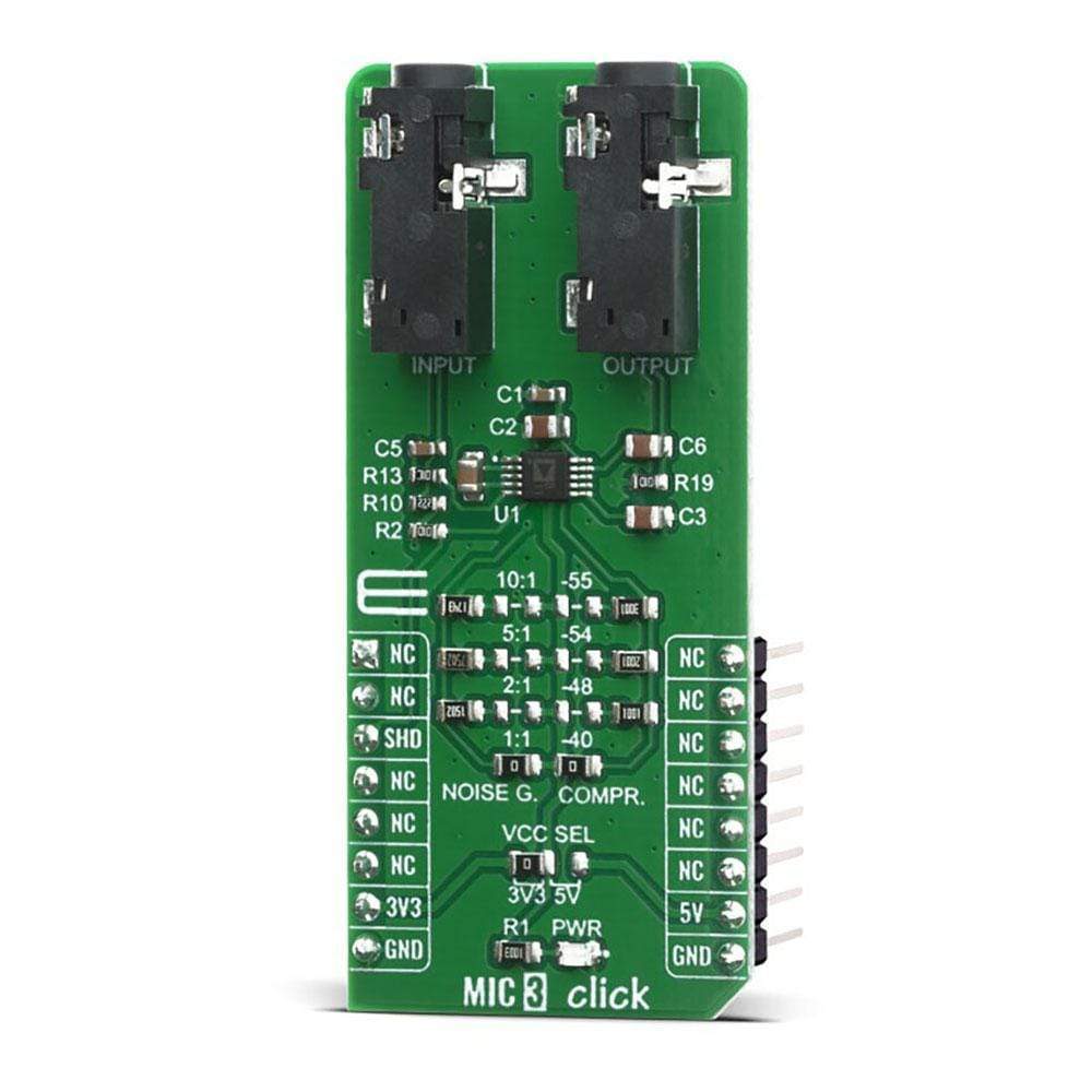
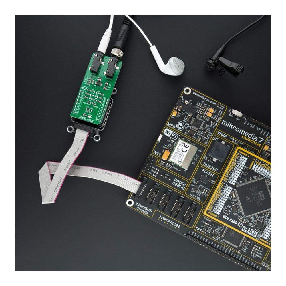
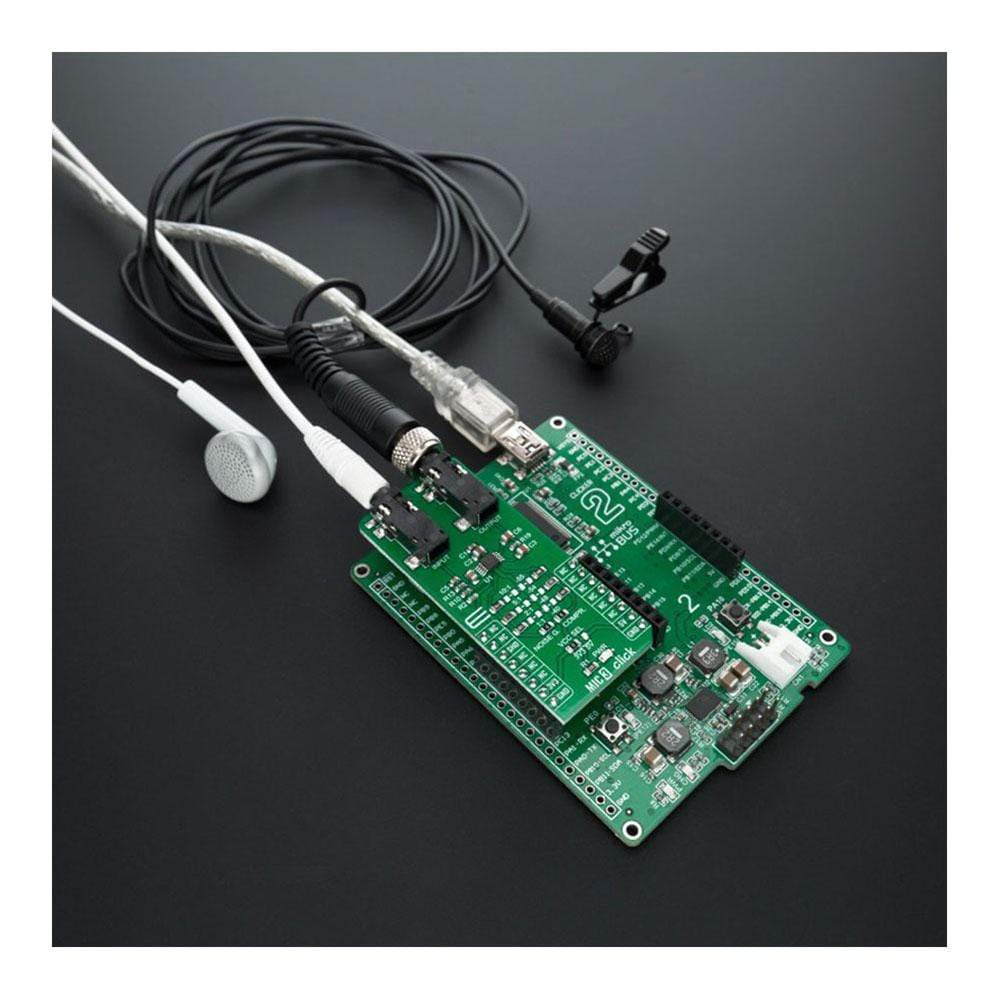
The MIC 3 Click Board™ features the SSM2167-1RMZ-R7, a Microphone Preamplifier, from Analog Device. This Click Board™ is a low voltage Microphone preamplifier with Variable compression and noise gating. The MIC 3 Click is a very easy solution to work with it, which makes it an ideal solution for using it in desktop, portable or palmtop computers, telephone conferencing, communication headsets, two-way communication, surveillance system where the microphone is needed, stethoscope, karaoke and DJ mixers.
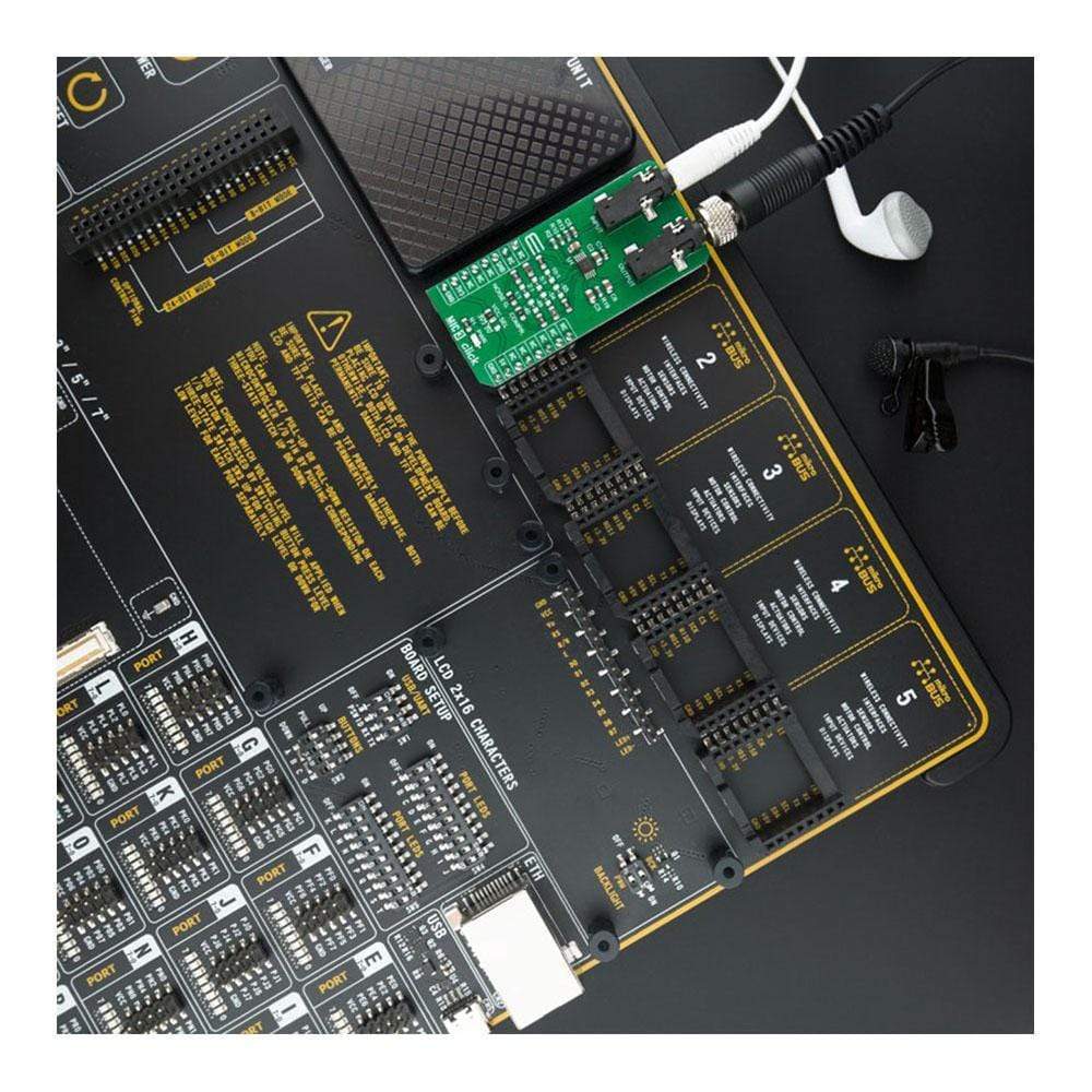
The MIC 3 Click Board™ is supported by a mikroSDK compliant library, which includes functions that simplify software development. This Click Board™ comes as a fully tested product, ready to be used on a system equipped with the mikroBUS™ socket.
Downloads
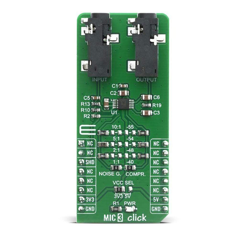
The MIC 3 Click Board™ is based on the SSM2167-1RMZ-R7 from Analog Devices is a complete and flexible solution for conditioning microphone inputs in personal electronics and computer audio systems. The Click board™ is also excellent for improving vocal clarity in communications and public address systems. A low noise voltage-controlled amplifier (VCA) provides a gain that is dynamically adjusted by a control loop to maintain a set compression characteristic. The MIC 3 Click provides two operation settings, these settings are selectable with NOISE G. COMPR. jumpers.
How Does The MIC 3 Click Board™ Work?
The MIC 3 Click Board™ provides four different preset values of the noise gate threshold. Experiment with these values by varying the gate. The noise gate threshold is a programmable point using an external resistor. The downward expansion threshold may be set between −40 dBV and −55 dBV, as shown in Table.
| Noise Gate (dBV) | Value of RGATE |
|---|---|
| -40 | 0 Ω |
| -48 | 1 Ω |
| -54 | 2 Ω |
| -55 | 3 Ω |
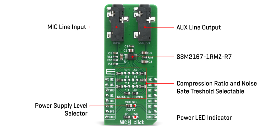
The MIC 3 Click Board™ provides four different preset values of the compression ratio. Changing the scaling of the control signal fed to the VCA causes a change in the circuit compression ratio. Lowering RCOMP gives smaller compression ratios as indicated in Table. Automatic Gain Control (AGC) performance is achieved with compression ratios between 2:1 and 10:1, and is dependent on the application. Shorting RCOMP disables the AGC function, setting the compression equal to 1:1.
| Compression Ratio | Value of RCOMP |
|---|---|
| 1:1 | 0 Ω |
| 2:1 | 15 Ω |
| 5:1 | 75 Ω |
| 10:1 | 174 Ω |
The MIC 3 Click Board™ is designed to work with either 3.3V or 5V power supply. It communicates with the target MCU over GPIO pin on the mikroBUS™. The supply current of the SSM2167 can be reduced to under 10 μA by applying an active low.
SPECIFICATIONS
| Type | Microphone |
| Applications | Karaoke and DJ mixers,Desktop, portable, or palmtop computers,Telephone conferencing. |
| On-board modules | SSM2167-1RMZ-R7, Low Voltage Microphone Preamplifier from Analog Device. |
| Key Features | Adjustable noise gate threshold,Adjustable compression ratio. |
| Interface | GPIO |
| Compatibility | mikroBUS |
| Click board size | L (57.15 x 25.4 mm) |
| Input Voltage | 3.3V or 5V |
PINOUT DIAGRAM
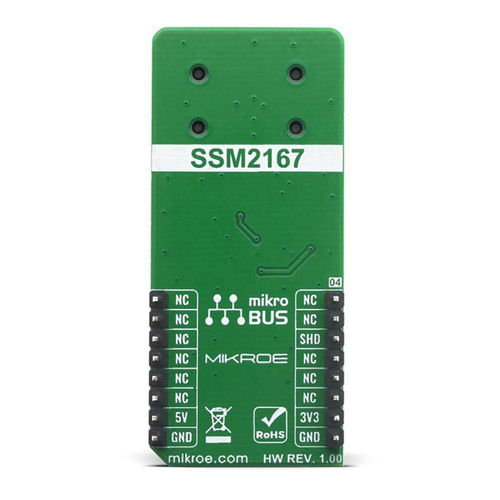
This table shows how the pinout of the MIC 3 Click Board™ corresponds to the pinout on the mikroBUS™ socket (the latter shown in the two middle columns).
| Notes | Pin |  |
Pin | Notes | |||
|---|---|---|---|---|---|---|---|
| NC | 1 | AN | PWM | 16 | NC | ||
| NC | 2 | RST | INT | 15 | NC | ||
| Shutdown | SHD | 3 | CS | RX | 14 | NC | |
| NC | 4 | SCK | TX | 13 | NC | ||
| NC | 5 | MISO | SCL | 12 | NC | ||
| NC | 6 | MOSI | SDA | 11 | NC | ||
| Power Supply | 3.3V | 7 | 3.3V | 5V | 10 | 5V | Power Supply |
| Ground | GND | 8 | GND | GND | 9 | GND | Ground |
ONBOARD SETTINGS AND INDICATORS
| Label | Name | Default | Description |
|---|---|---|---|
| LD1 | PWR | - | Power LED Indicator |
| - | NOISE G. COMPR | 1:1, -40 | Select noise gate threshold and compression ratio. |
| General Information | |
|---|---|
Part Number (SKU) |
MIKROE-4136
|
Manufacturer |
|
| Physical and Mechanical | |
Weight |
0.021 kg
|
| Other | |
Country of Origin |
|
HS Code Customs Tariff code
|
|
EAN |
8606018717682
|
Warranty |
|
Frequently Asked Questions
Have a Question?
Be the first to ask a question about this.


