


Mikroelektronika d.o.o.
9DOF 2 Click Board™
9DOF 2 Click Board™
SKU: MIKROE-4128
Couldn't load pickup availability


Overview
The 9DOF 2 Click Board™ is a compact add-on board for applications that require the lowest power motion tracking and magnetometer functionality. This board features the ICM-20948 a 9-axis MotionTracking™ sensor from TDK Invensense, which consist of two sensors combined into one package for a universal 9DOF solution. In this package, we have a 3-axis gyroscope, a 3-axis accelerometer, a 3-axis magnetometer, combined with Digital Motion Processor™ (DMP) and run-time calibration firmware. All these features make the 9DOF 2 Click Board™ an excellent choice for manufacturers looking for a product to eliminate the costly and complex selection, qualification, and system-level integration of discrete devices, guaranteeing optimal motion performance for consumers. Its also ideally suited for wearable sensors and IoT applications needed low power motion tracking device expandable with additional I2C sensors.
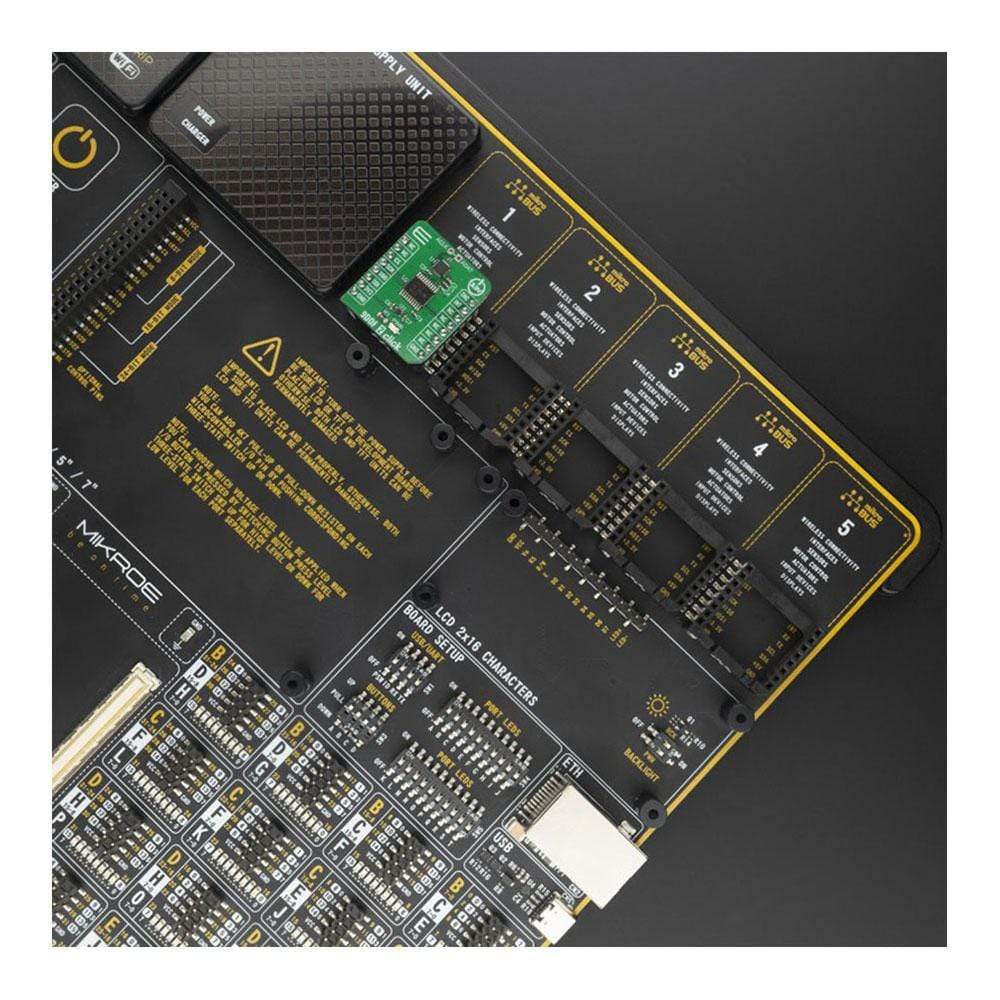
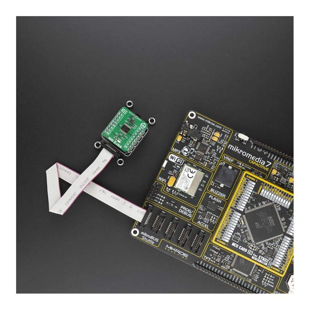
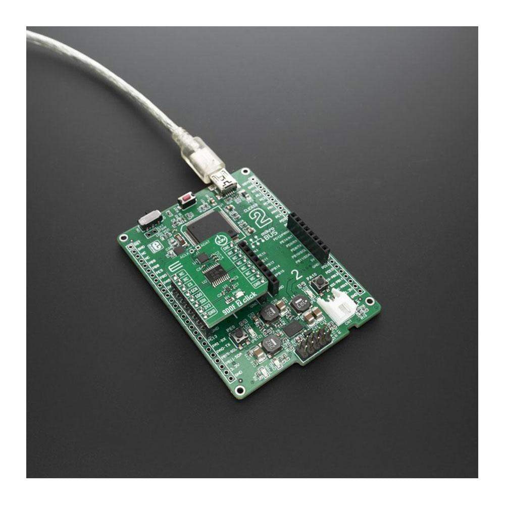
The 9DOF 2 Click Board™ is supported by a mikroSDK compliant library, which includes functions that simplify software development. This Click Board™ comes as a fully tested product, ready to be used on a system equipped with the mikroBUS™ socket.
Downloads
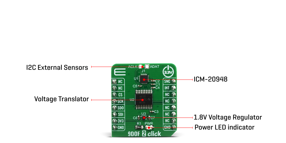
How Does The 9DOF 2 Click Board™ Work?
The 9DOF 2 Click Board™ is based on the ICM-20948, a high performance, 9-axis MotionTracking™ IC from TDK Invensense. ICM-20948 also supports an auxiliary I2C interface to external sensors which offer greater system flexibility. The output of each MEMS is processed and digitized by a separate sigma-delta 16-bit A/D converter (ADC). Three-axis gyroscope MEMS can be programmed to measure the rotation about each axis, in four different ranges of rotational speed (degrees per angle, DPS): ±250, ±500, ±1000, and ±2000. Three-axis accelerometer MEMS can be programmed to measure the acceleration along each axis, in four different acceleration ranges: ±2g, ±4g, ±8g, and ±16g. A three-axis magnetometer can do a full-scale measurement of ±4900 µT.
Interrupt functionality is configured via the Interrupt Configuration register. Items that are configurable include the INT pin configuration, the interrupt latching and clearing method, and triggers for the interrupt. The interrupt is routed to the INT pin of the mikroBUS™.
A FIFO buffer helps to further reduce the processing load, offering temporary storage for the output data. The ICM-20948 contains a FIFO of size 512 bytes (FIFO size will vary depending on DMP feature-set) that is accessible via the Serial Interface. The FIFO configuration register determines which data is written into the FIFO. Possible choices include gyro data, accelerometer data, temperature readings, auxiliary sensor readings, and FSYNC input. Synchronization with an external digital signal is possible over the FSYNC pin. This pin is routed to the PWM pin of the mikroBUS™, labelled as SNC.
The embedded Digital Motion Processor (DMP) within the ICM-20948 offloads computation of motion processing algorithms from the host processor. The DMP acquires data from accelerometers, gyroscopes, and additional third-party sensors such as magnetometers, and processes the data. The resulting data can be read from the FIFO. The DMP has access to the external pins, which can be used for generating interrupts.
ICM-20948 supports both SPI and I2C communication interfaces but only SPI interface is used on the 9DOF 2 Click. The voltage level conversion between ICM-20948 and 3.3V MCU is done by the TXB0108 bidirectional voltage-level translator.
The 9DOF 2 Click Board™ uses only the SPI communication interface. It is designed to be operated only with 3.3V logic levels. A proper logic voltage level conversion should be performed before the Click board™ is used with MCUs with logic levels of 5V.
SPECIFICATIONS
| Type | Gyroscope,Magnetic,Motion |
| Applications | Can be used for Smartphones and Tablets, wearable sensors and IoT Applications. |
| On-board modules | The 9DOF 2 Click Board™ uses the ICM-20948 IC, the world's lowest power 9-axis MotionTracking device, from TDK Invensense. |
| Key Features | Mobile phones, tablet PCs, GPS systems, Smartwatches, Sport and fitness devices, and many more. |
| Interface | SPI |
| Compatibility | mikroBUS |
| Click board size | S (28.6 x 25.4 mm) |
| Input Voltage | 3.3V |
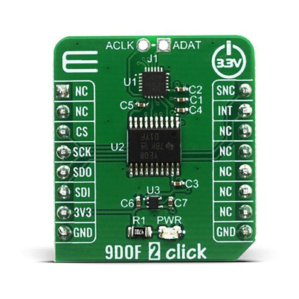
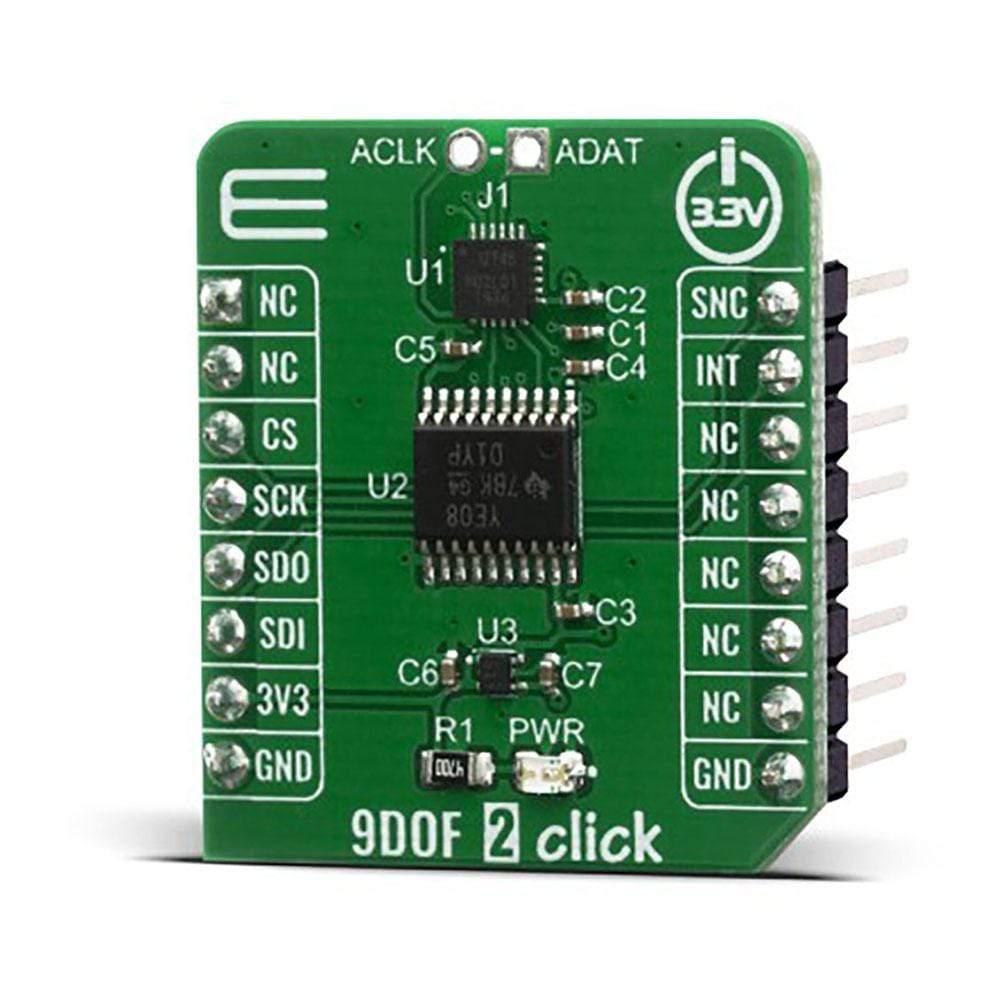
PINOUT DIAGRAM
This table shows how the pinout of the 9DOF 2 Click Board™ corresponds to the pinout on the mikroBUS™ socket (the latter shown in the two middle columns).
| Notes | Pin | Pin | Notes | ||||
|---|---|---|---|---|---|---|---|
| NC | 1 | AN | PWM | 16 | SYN | External sync | |
| NC | 2 | RST | INT | 15 | INT | Interrupt | |
| SPI Chip Select | CS | 3 | CS | RX | 14 | NC | |
| SPI Clock | SCK | 4 | SCK | TX | 13 | NC | |
| SPI Data OUT | SDO | 5 | MISO | SCL | 12 | NC | |
| SPI Data IN | SDI | 6 | MOSI | SDA | 11 | NC | |
| Power Supply | 3.3V | 7 | 3.3V | 5V | 10 | NC | |
| Ground | GND | 8 | GND | GND | 9 | GND | Ground |
ONBOARD SETTINGS AND INDICATORS
| Label | Name | Default | Description |
|---|---|---|---|
| LD1 | PWR | - | Power LED Indicator |
| General Information | |
|---|---|
Part Number (SKU) |
MIKROE-4128
|
Manufacturer |
|
| Physical and Mechanical | |
Weight |
0.018 kg
|
| Other | |
EAN |
8606018717538
|
Frequently Asked Questions
Have a Question?
Be the first to ask a question about this.