


Mikroelektronika d.o.o.
Stepper 14 Click Board™
Stepper 14 Click Board™
SKU: MIKROE-4125
Couldn't load pickup availability
Overview
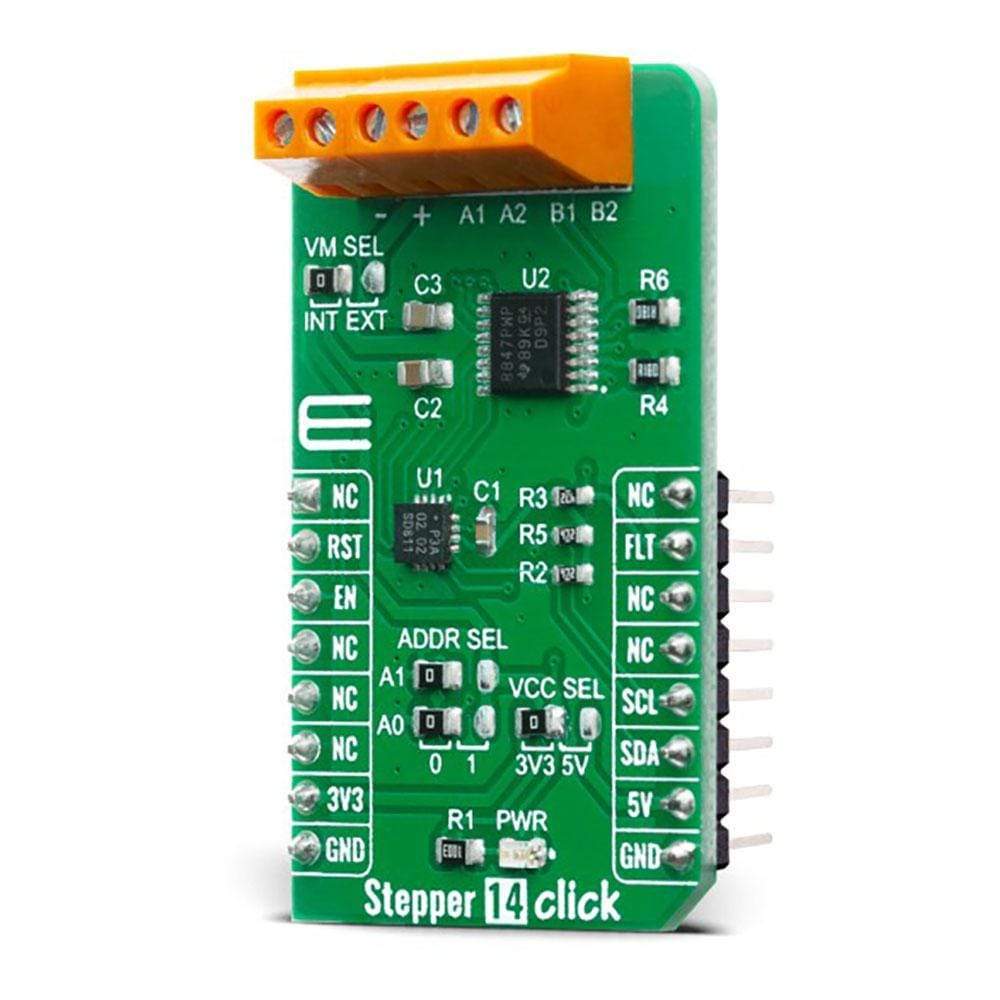
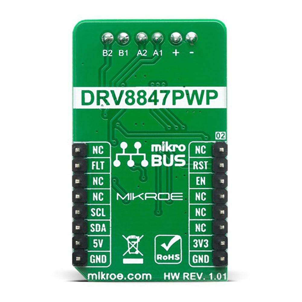
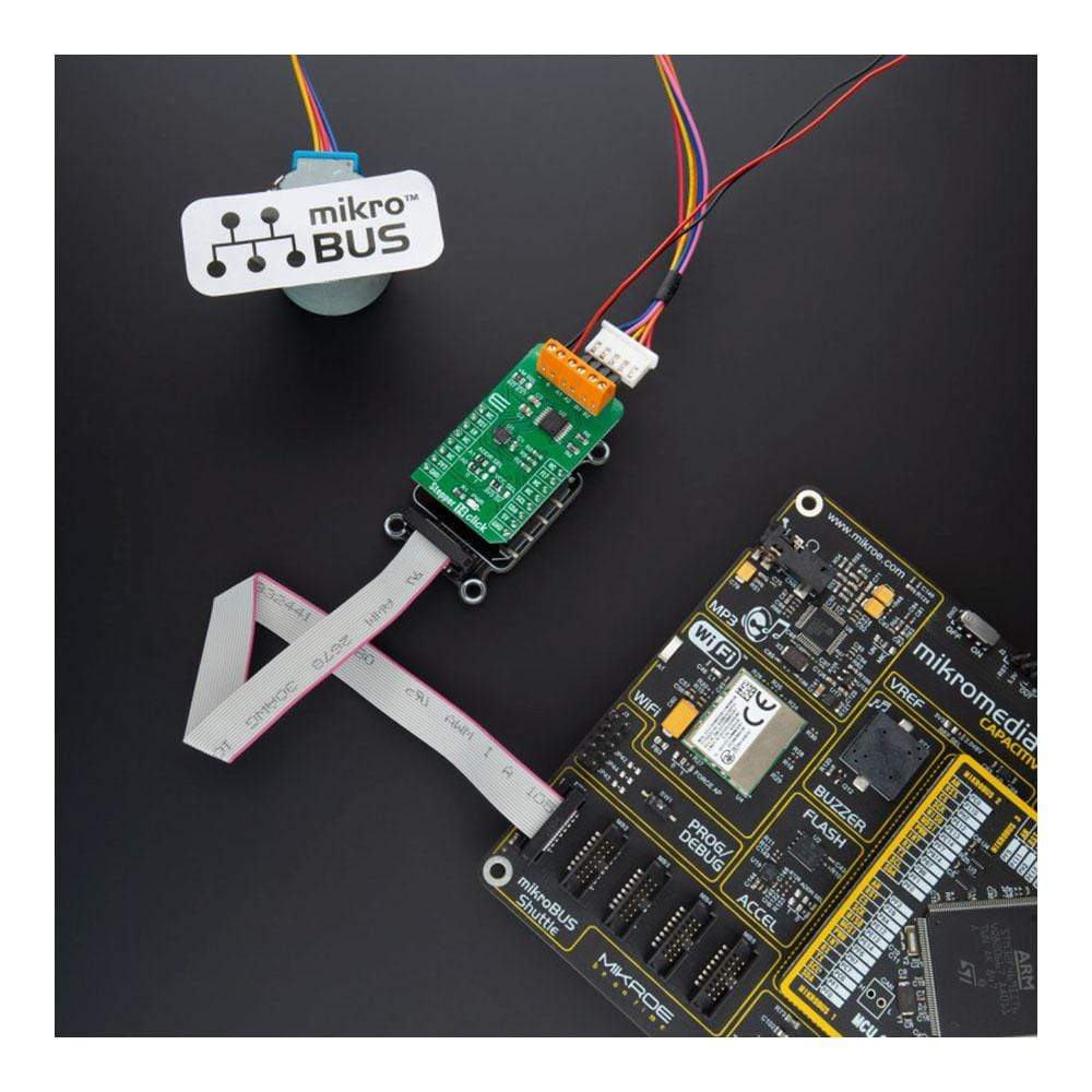
The Stepper 14 Click Board™ features the DRV8847PWPR, a step motor driver, from Texas Instruments. This Click Board™ provides a bipolar step motor controle, It features an H-bridge bipolar step motor driver, which supports full-, half-, quarter-, or eighth-step modes. This Click Board™ also carries a port expander so that the communication can be done with a minimal number of pins, through the mikroBUS™ I2C bus.
The Stepper 14 Click Board™ offers thermal protection, integrated kickback voltage protection, it has a wide range of input voltage, protection against current shoot-through the H-Bridge and high current capability. These features make Stepper 14 Click Board™ an ideal solution for driving motors in any application that demands a precise and safe step motor driver.
Downloads
How Does The Stepper 14 Click Board™ Work?
The Stepper 14 Click Board™ is equipped with two integrated circuits. The step motor driver IC is the DRV8847PWPR, a dual full-bridge motor driver from Texas Instruments. This IC internal structure is somewhat symmetrical. It features two MOSFET H-bridges used to drive two coils of a bipolar step motor in both directions. The DRV8847PWPR uses a wide input voltage range - from 2.7V to 18V. This is the voltage used to energize the motor coils. A jumper (JP4) is used to select whether to use external power supply or to obtain the power supply from the mikroBUS™ +3.3V or +5V rail. The DRV8847PWPR has two PHASE inputs which are used to control the direction of current flow through H-bridges and thus, the motor coils. It also allows controlling step motor in both full step and half step modes, by toggling states on MS1 and MS1 pins.
.jpg)
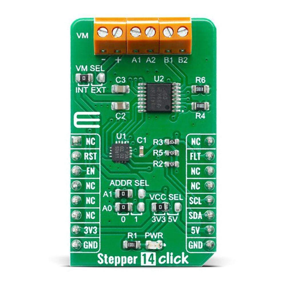
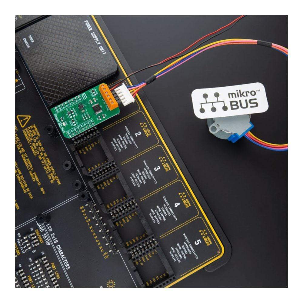
The bipolar step motor coils can be connected to the onboard screw terminals. There are two terminals, used to connect each of the step motor coils. The third connector is used to connect an external voltage, ranging from 2.7V to 18V, depending on the used motor voltage requirements. It should be noted that without a valid external voltage connected to this terminal, the motor will not work. Also, it should be noted that 20V is an absolute maximum voltage allowed as per datasheet, thus the overtemperature protection might be activated when driving heavier loads. The recommended maximum voltage should not exceed 18V, as stated on the silkscreen layer of the PCB.
All of the DRV8847PWPR control lines are routed to the second IC on Stepper 14 board, which is the PCA9538A, a well-known 8bit I/O expander with a serial interface, used on many of the MikroElektronika's designs for its simplicity and reliability. It allows the control lines of the DRV8847PWPR IC to be driven via the I2C and few pins it uses - reducing the required pin count of the Stepper 14 Click Board™. This also allows for sending compact I2C messages, instead of toggling several pins at once - which can introduce problems with timing sometimes, especially when those pins belong to different MCU ports. By changing states of the six control pins, it is possible to drive the step motor in full step mode as well as the half step mode. However, provided MikroElektronika libraries contain simple and intuitive functions to fully control the bipolar step motor, connected to the Stepper 14 Click Board™. Their usage is demonstrated in the included example application, which can be used as a reference for a custom design.
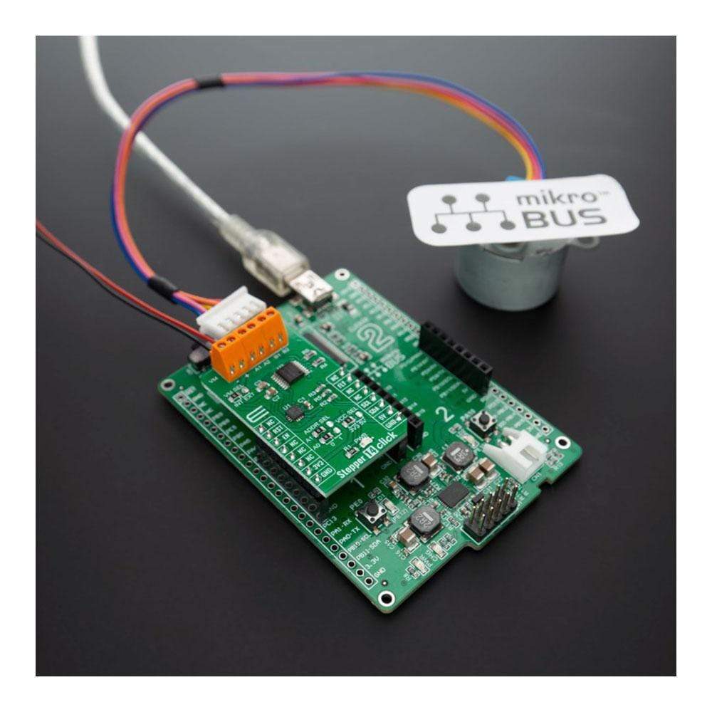
The motor power supply can be connected to the input terminal labelled as VIN and should be within the range of 2.7V to 18V. Stepper motor coils can be connected to the terminals labelled as A1, B2, B1, and A2. The Click board™ supports an optional external power supply for the motor in order to work.
However, the Stepper 14 Click Board™ can be supplied and interfaced with both 3.3V and 5V without the need for any external components. The onboard SMD jumper labelled as VCC SEL allows voltage selection for interfacing with both 3.3V and 5V microcontrollers.
SPECIFICATIONS
| Type | Stepper |
| Applications | Refrigerator damper and ice maker, Washers, dryers and dishwashers, Electronic point-of-sale (ePOS) printers , Stage lighting equipment, Miniature circuit breakers and smart meters etc. |
| On-board modules | DRV8847PWPR Dual Full-Bridge 18V, 1A, Stepper Motor Driver, from Texas Instruments; PCA9538A 8bit I/O Expander with Serial Interface, from NXP |
| Key Features | Dual H-bridge motor driver, Single or dual brushed DC motors, One bipolar stepper motor, Solenoid loads, Multiple control interface options. |
| Interface | GPIO,I2C |
| Compatibility | mikroBUS |
| Click board size | M (42.9 x 25.4 mm) |
| Input Voltage | 3.3V or 5V |
PINOUT DIAGRAM
This table shows how the pinout of the Stepper 14 Click Board™ corresponds to the pinout on the mikroBUS™ socket (the latter shown in the two middle columns).
| Notes | Pin | Pin | Notes | ||||
|---|---|---|---|---|---|---|---|
| NC | 1 | AN | PWM | 16 | NC | ||
| Reset In | RST | 2 | RST | INT | 15 | FLT | Fault |
| Enable | EN | 3 | CS | RX | 14 | NC | |
| NC | 4 | SCK | TX | 13 | NC | ||
| NC | 5 | MISO | SCL | 12 | SCL | I2C Clock | |
| NC | 6 | MOSI | SDA | 11 | SDA | I2C Data | |
| Power Supply | 3.3V | 7 | 3.3V | 5V | 10 | 5V | Power Supply |
| Ground | GND | 8 | GND | GND | 9 | GND | Ground |
ONBOARD SETTINGS AND INDICATORS
| Label | Name | Default | Description |
|---|---|---|---|
| LD1 | PWR | - | Power LED Indicator |
| JP1 | VCC SEL | Left | Power Supply Voltage Selection: Left position 3V3, right position 5V |
| JP2 | ADDR SEL | Left | Slave address selection: Left position 0, right position 1. |
| JP3 | ADDR SEL | Left | Slave address selection: Left position 0, right position 1. |
| JP4 | VM SEL | Left | Power select jumper for motor power supply: left position - On-board supply, right position - External supply. |
STEPPER 14 CLICK ELECTRICAL SPECIFICATIONS
| Description | Min | Typ | Max | Unit |
|---|---|---|---|---|
| Input Voltage | 2.7 | - | 18 | V |
| Output current | - | - | 1 | A |
| General Information | |
|---|---|
Part Number (SKU) |
MIKROE-4125
|
Manufacturer |
|
| Physical and Mechanical | |
Weight |
0.019 kg
|
| Other | |
EAN |
8606018717514
|
Frequently Asked Questions
Have a Question?
Be the first to ask a question about this.