


Mikroelektronika d.o.o.
Analog MUX Click Board™
Analog MUX Click Board™
SKU: MIKROE-4111
Couldn't load pickup availability


Key Features
Overview
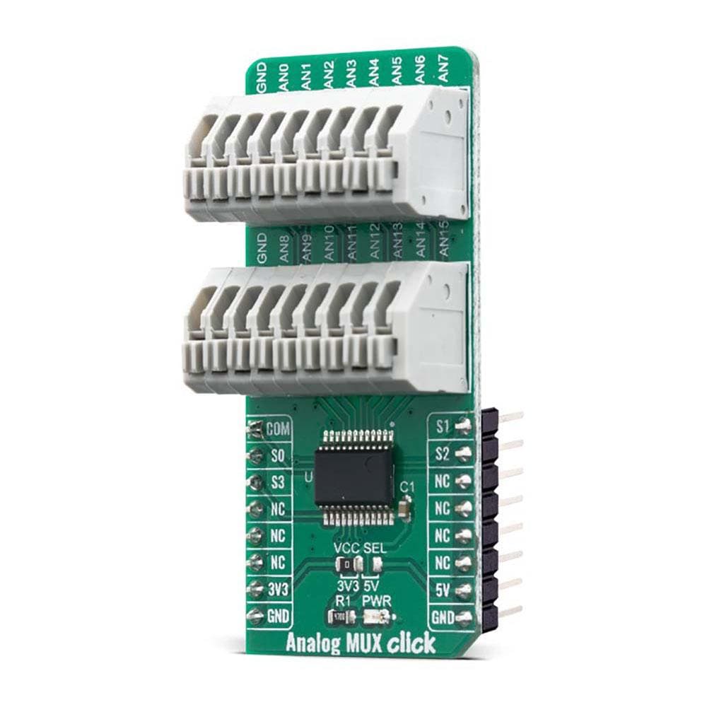
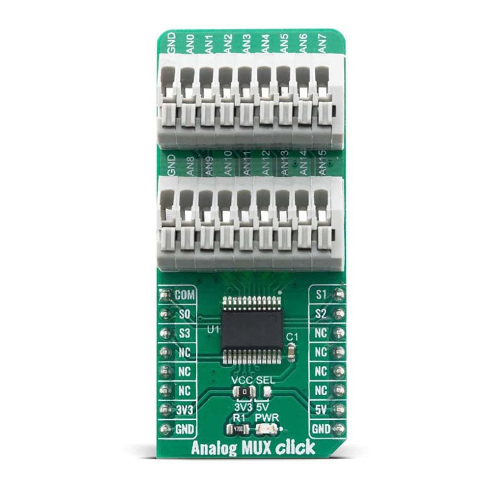
The Analog MUX Click Board™ switches one of the sixteen inputs to one output. It employs the CD74HC4067, a High-Speed CMOS Logic 16-Channel Analog Multiplexer/Demultiplexer, produced by Texas Instruments. It offers rail-to-rail operation, allowing the input signal to swing up (and down) to the voltage of the power supply, with no distortion.
Features such as the low on-resistance and low input current leakage, fast and balanced propagation delay and transition times and break-before-make switching action make this circuit a perfect solution for various switching applications, analogue and digital signals.
Downloads
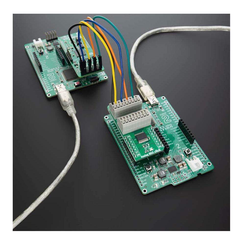
How Does The Analog MUX Click Board™ Work?
The Analog MUX Click Board™ is equipped with the CD74HC4067, a high-speed CMOS logic 16-channel analog multiplexer/demultiplexer, produced by Texas Instruments. It supports 3.3V and 5V power supplies, as well as rail to rail operation, which allows it to be used in a very wide range of different applications. Four control pins are used to switch one of sixteen inputs to a single output. Control pins labeled as S0, S1, S2, and S3 are routed to the mikroBUS™ and can be operated by both 3.3V and 5V MCUs. These pins are routed to RST, PWM, INT, and CS pins of the mikroBUS™ respectively, while the common output pin from the multiplexer is routed to the AN pin on the mikroBUS™.
The CD74HC4067 IC is digitally controlled analog switch that utilize silicon-gate CMOS technology to achieve operating speeds similar to LSTTL, with the low power consumption of standard CMOS integrated circuits. The mentioned analog multiplexer/demultiplexer control analog voltages that may vary across the voltage supply range.
The ultra-low leakage current ensures that there is no signal interference from the inputs that are not selected by the S0, S1, S2, and S3 pins. A low crosstalk also ensures that the signal on one channel remains clean of interferences caused by other channels. To prevent any two inputs to be switched at the output at the same time, a break-before-make switching action is utilized. This ensures a reliable operation of the IC and the Click board™ itself. The Analog MUX Click Board™ is bidirectional switch as well, thus allowing any analog input to be used as an output and vice-versa. The switches have low "on" resistance and low "off" leakages.
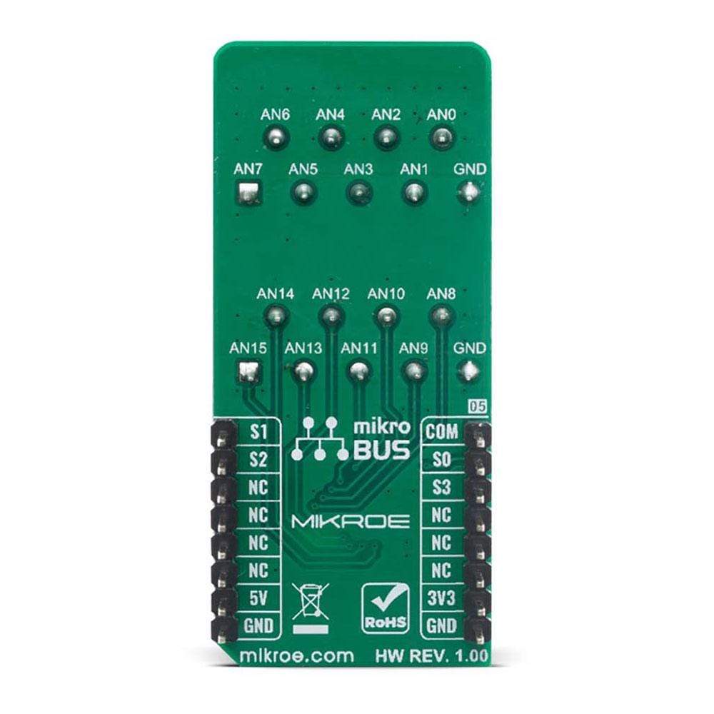
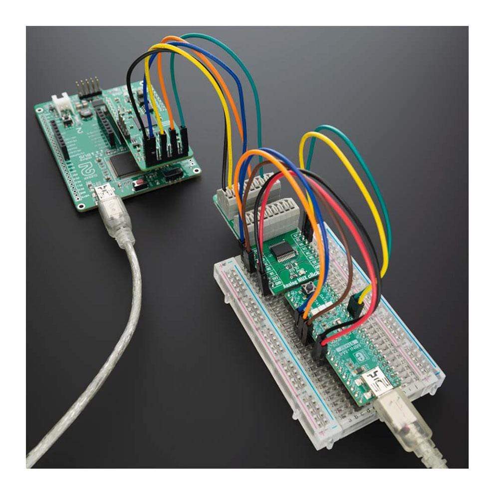
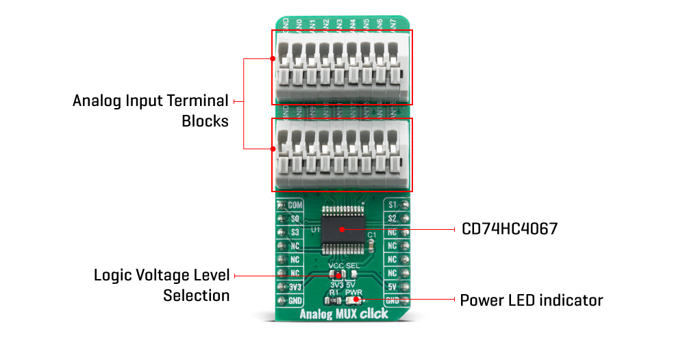
All of the input channels can be easily connected to the two 9 pole spring action block terminals, without having to use any additional tools, such as screwdrivers.
More information about the CD74HC4067 can be found in the attached datasheet. However, the Analog MUX Click Board™ comes equipped with a library that contains easy to use functions and a usage example that may be used as a reference for the development.
The Analog MUX Click Board™ offers a selection between 3.3V and 5V operation, with the onboard SMD jumper, labeled as PWR SEL. This allows both 3.3V and 5V MCUs to be interfaced with this Click board™.
SPECIFICATIONS
| Type | Port expander |
| Applications | Automatization and process control, programmable logic controllers, digital multimeters, battery monitoring, and other applications that require analog signal switching. |
| On-board modules | CD74HC4067, a high-speed CMOS logic 16-channel analog multiplexer/demultiplexer, produced by Texas Instruments. |
| Key Features | low on-resistance and low input current leakage, fast and balanced propagation delay and transition times, break-before-make switching action |
| Interface | GPIO |
| Compatibility | mikroBUS |
| Click board size | L (57.15 x 25.4 mm) |
| Input Voltage | 3.3V or 5V |
PINOUT DIAGRAM
This table shows how the pinout for the Analog MUX Click Board™corresponds to the pinout on the mikroBUS™ socket (the latter shown in the two middle columns).
| Notes | Pin | Pin | Notes | ||||
|---|---|---|---|---|---|---|---|
| Common output pin | COM | 1 | AN | PWM | 16 | S1 | Control pin 1 |
| Control pin 0 | SO | 2 | RST | INT | 15 | S2 | Control pin 2 |
| Control pin 3 | S3 | 3 | CS | RX | 14 | NC | |
| NC | 4 | SCK | TX | 13 | NC | ||
| NC | 5 | MISO | SCL | 12 | NC | ||
| NC | 6 | MOSI | SDA | 11 | NC | ||
| Power Supply | 3.3V | 7 | 3.3V | 5V | 10 | 5V | Power Supply |
| Ground | GND | 8 | GND | GND | 9 | GND | Ground |
ONBOARD SETTINGS AND INDICATORS
| Label | Name | Default | Description |
|---|---|---|---|
| LD1 | PWR | - | Power LED Indicator |
| JP1 | VCC SEL | Left | Power Supply Voltage Selection 3V3/5V, left position 3v3, right position 5v |
| TB1, TB2 | - | - | Input 9 pole spring action terminals |
ANALOG MUX CLICK ELECTRICAL SPECIFICATIONS
| Description | Min | Typ | Max | Unit |
|---|---|---|---|---|
| VCC | 2 | 3.3 | 6 | V |
| "ON" Resistance | 70 | Ω | ||
| Input Rise and Fall Time | 500 | ns |
| General Information | |
|---|---|
Part Number (SKU) |
MIKROE-4111
|
Manufacturer |
|
| Physical and Mechanical | |
Weight |
0.02 kg
|
| Other | |
EAN |
8606018717415
|
Frequently Asked Questions
Have a Question?
Be the first to ask a question about this.