


Mikroelektronika d.o.o.
ADC 9 Click Board™
ADC 9 Click Board™
SKU: MIKROE-4105
Couldn't load pickup availability


Key Features
Overview
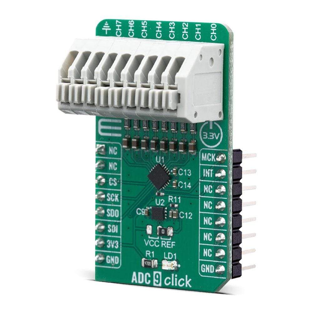
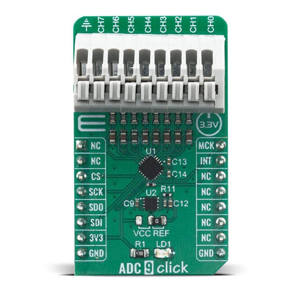
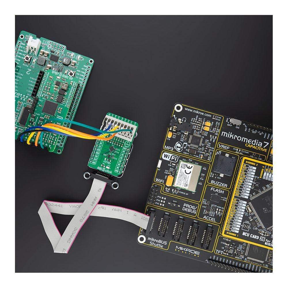
The ADC 9 Click Board™ is the 8th channel analogue to digital converter expansion board, for projects where you have demand for multi-channel ADC conversions such as microcontrollers with a small number or no analogue inputs. This Click board is based on MCP3564 a 24-bit Delta-Sigma Analog-to-Digital Converter with a programmable data rate of up to 153.6 KSPS from Microchip. It offers integrated features, such as an internal oscillator, temperature sensor and burnout sensor detection, in order to reduce system component count and total solution cost. An ideal choice for precision data acquisition systems, high-resolution data converters, industrial control, battery-powered devices and many more.
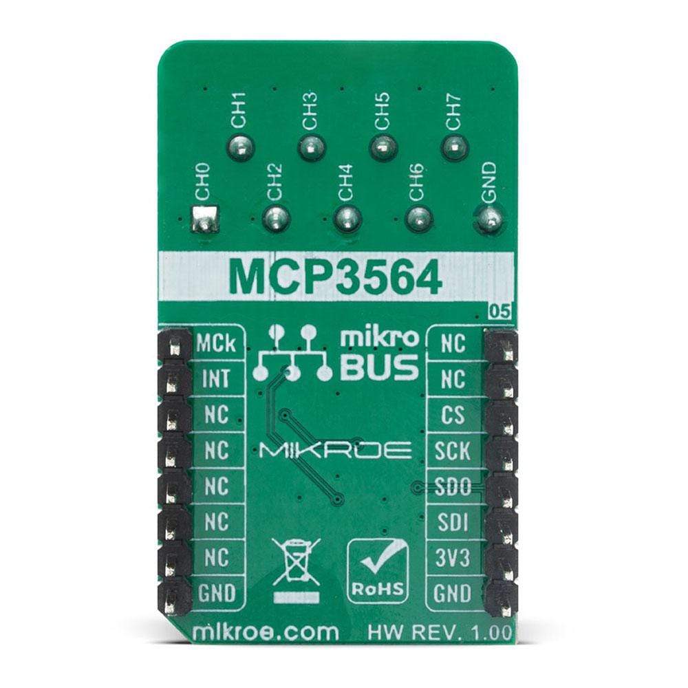
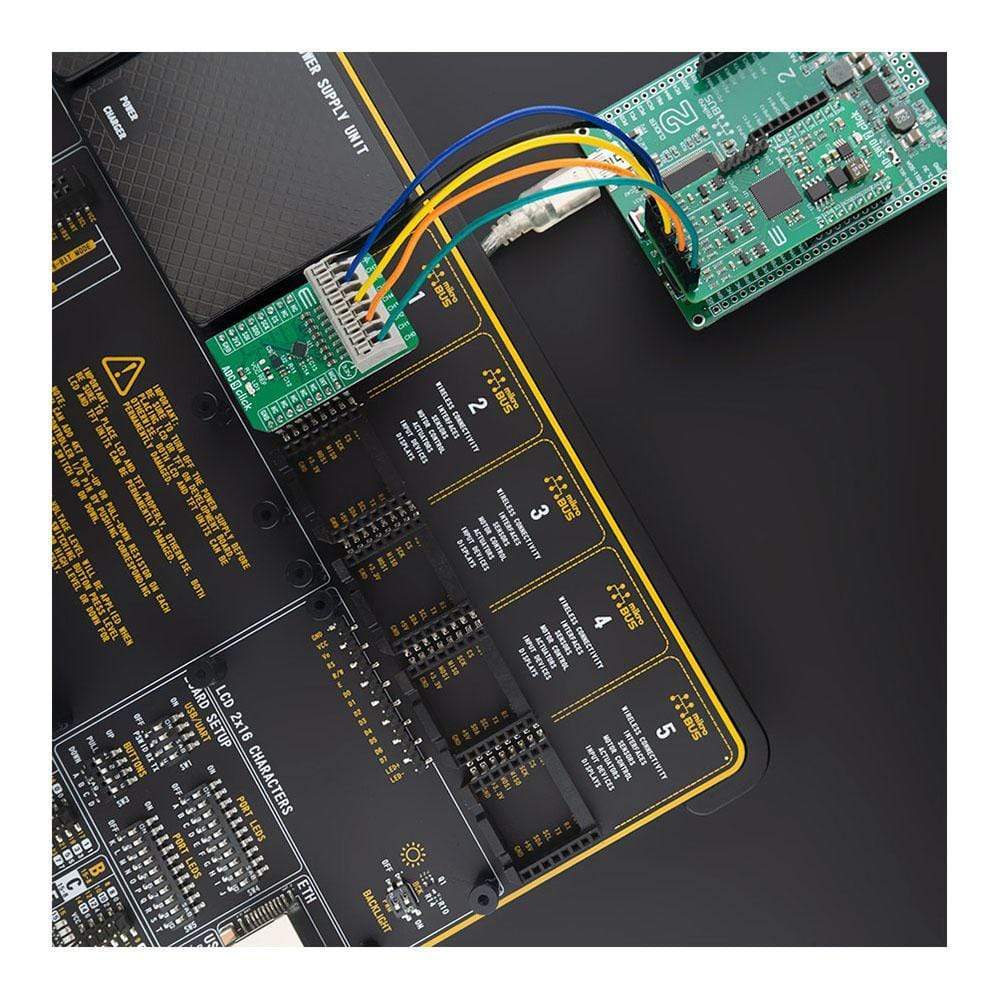
The ADC 9 Click Board™ is supported by a mikroSDK compliant library, which includes functions that simplify software development. This Click Board™ comes as a fully tested product, ready to be used on a system equipped with the mikroBUS™ socket.
Downloads
How Does The ADC 9 Click Board™ Work?
The MCP3564 24-bit Delta-Sigma Analog-to-Digital Converter is fully configurable with Oversampling Ratio (OSR) from 32 to 98304 and gain from 1/3x to 64x. It include an internal sequencer (SCAN mode) with multiple monitor channels and a 24-bit timer to be able to automatically create conversion loop sequences without needing MCU communications. Advanced security features, such as CRC and register map lock, can ensure configuration locking and integrity, as well as communication data integrity for secure environments.
The ADC 9 Click Board™ comes with a 20 MHz SPI-compatible serial interface. Communication is largely simplified with 8-bit commands, including various Continuous Read/Write modes and 24/32-bit multiple data formats that can be accessed by the Direct Memory Access (DMA) of an 8-bit, 16-bit or 32-bit MCU.
The noise value generally increases when temperature is higher as thermal noise is dominant for all OSR larger than 32. For high OSR settings (> 512), the thermal noise is largely dominant and increases proportionally to the square root of the absolute temperature. The noise performance is also a function of the measurement duration. For short duration measurements (low number of consecutive samples), the peak-to-peak noise is usually reduced because the crest factor (ratio between the RMS noise and peak-to-peak noise) is reduced. This is only a consequence of the noise distribution being Gaussian by nature.
The ADC 9 Click Board™ uses the MCP3564 IC with a fully configurable analog input dual multiplexer that can select which input is connected to each of the two differential input pins (VIN+/VIN-) of the Delta-Sigma ADC. Each of these multiplexers includes the same possibilities for the input selection, so that any required combination of input voltages can be converted by the ADC. The analog multiplexer is composed of parallel low-resistance input switches turned on or off depending on the input channel selection. Their resistance is negligible compared to the input impedance of the ADC (caused by the charge and discharge of the input sampling capacitors on the VIN+/VIN- ADC inputs).
The ADC 9 Click Board™ also features MCP1501-20, a low drift bandgap-based voltage reference from Microchip for precision data acquisition systems. The bandgap uses chopper-based amplifiers, effectively reducing the drift to zero.
It is designed to be operated only with 3.3V logic levels. A proper logic voltage level conversion should be performed before the ADC 9 Click Board™ is used with MCUs with logic levels of 5V.
SPECIFICATIONS
| Type | ADC |
| Applications | Can be used for an analog to digital conversion in various applications, such as precise temperature, strain, flow, force measurement and pressure measurement, manufacturing process control, precise instrumentation in general, and for similar applications |
| On-board modules | MCP3564 |
| Key Features | 24-Bit Resolution, Four Differential or Eight Single-Ended Input Channels, Low-Temperature Drift, 24-Bit Digital Offset and Gain Error Calibration Registers and many more eight analog input channels |
| Interface | GPIO,SPI |
| Compatibility | mikroBUS |
| Click board size | M (42.9 x 25.4 mm) |
| Input Voltage | 3.3V |
PINOUT DIAGRAM
This table shows how the pinout on the ADC 9 Click Board™ corresponds to the pinout on the mikroBUS™ socket (the latter shown in the two middle columns).
| Notes | Pin | Pin | Notes | ||||
|---|---|---|---|---|---|---|---|
| NC | 1 | AN | PWM | 16 | MCK | Master Clock | |
| NC | 2 | RST | INT | 15 | INT | Interrupt/Modulator Data | |
| SPI Chip Select | CS | 3 | CS | RX | 14 | NC | |
| SPI Clock | SCK | 4 | SCK | TX | 13 | NC | |
| SPI Data OUT | SDO | 5 | MISO | SCL | 12 | NC | |
| SPI Data IN | SDI | 6 | MOSI | SDA | 11 | NC | |
| Power Supply | 3.3V | 7 | 3.3V | 5V | 10 | NC | |
| Ground | GND | 8 | GND | GND | 9 | GND | Ground |
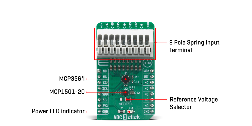
ONBOARD SETTINGS AND INDICATORS
| Label | Name | Default | Description |
|---|---|---|---|
| LD1 | PWR | - | Power LED Indicator |
| VOLT SEL | JP1 | Right | Voltage Reference Selector (Left VCC, Right 2.048V) |
| General Information | |
|---|---|
Part Number (SKU) |
MIKROE-4105
|
Manufacturer |
|
| Physical and Mechanical | |
Weight |
0.021 kg
|
| Other | |
EAN |
8606018717385
|
Frequently Asked Questions
Have a Question?
Be the first to ask a question about this.