


Mikroelektronika d.o.o.
6DOF IMU 12 Click Board™
6DOF IMU 12 Click Board™
SKU: MIKROE-4073
Couldn't load pickup availability
Overview
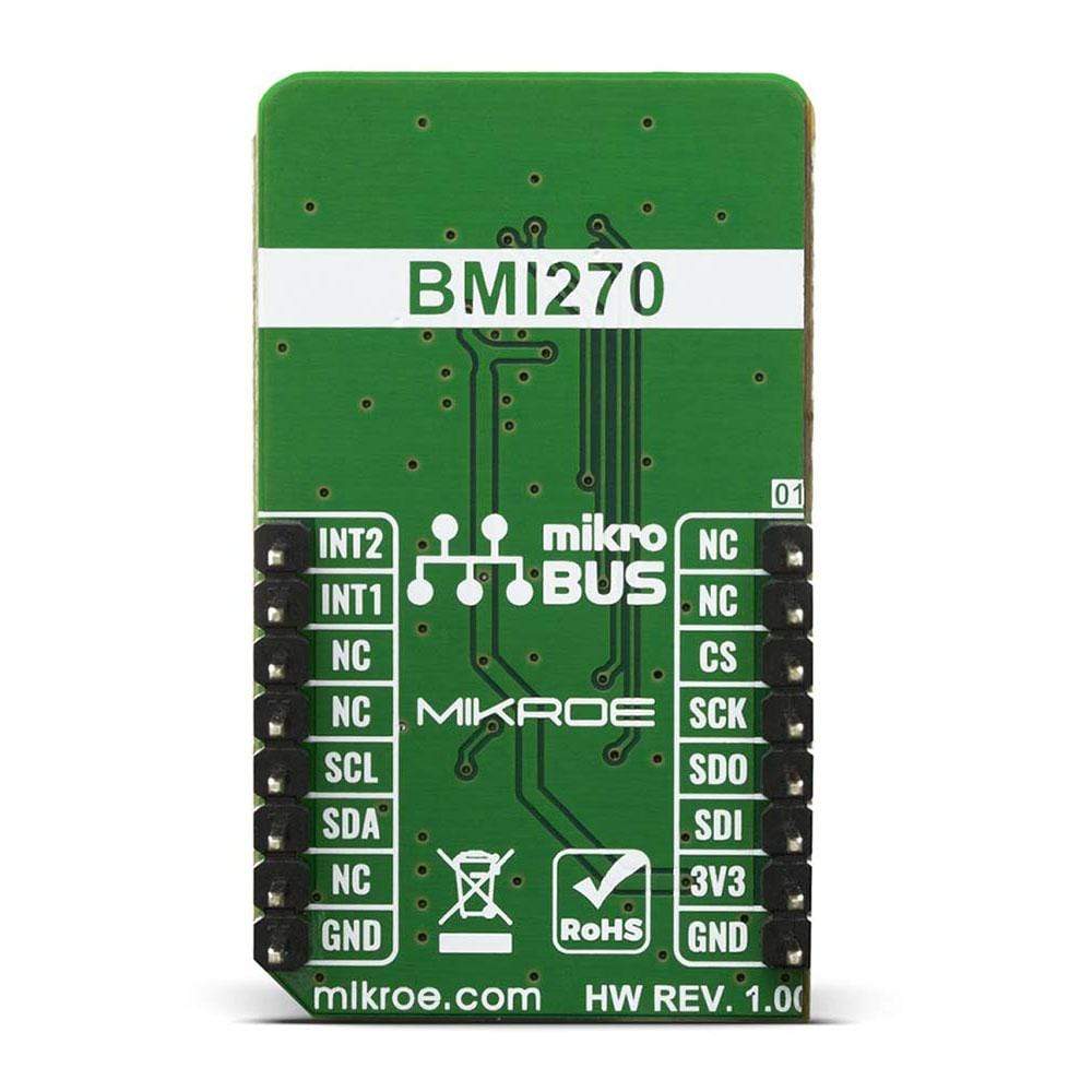
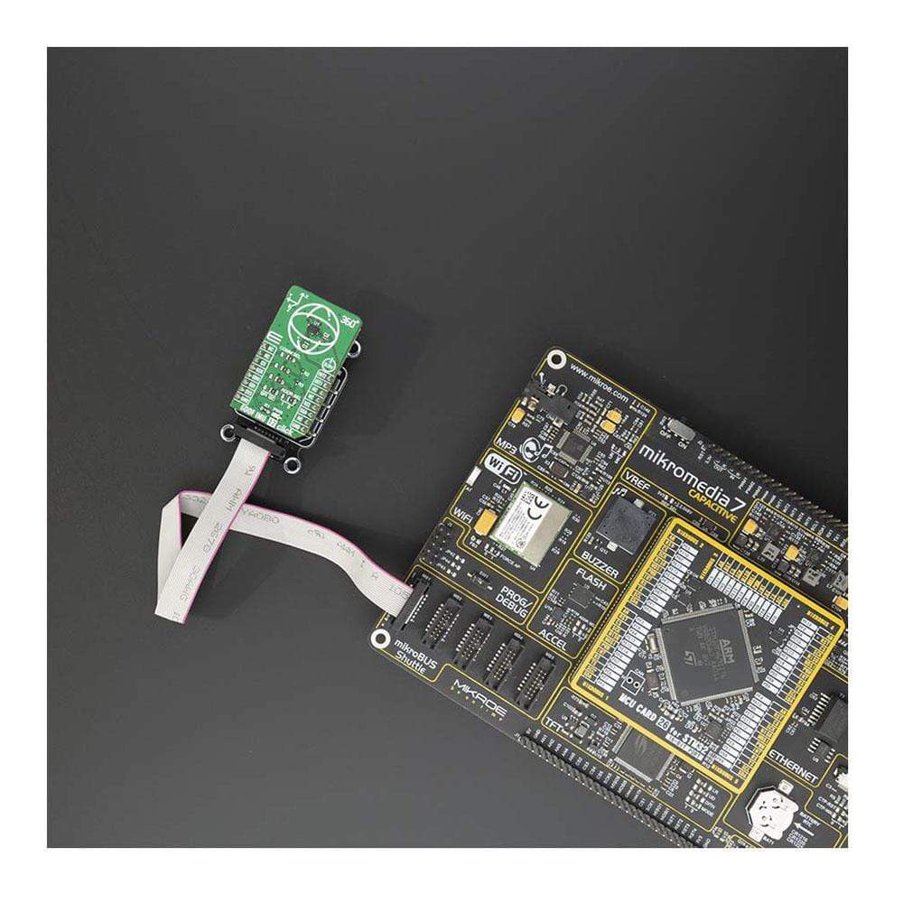
The 6DOF IMU 12 Click Board™ carries the ultra-low-power BMI270 from Bosch Sensortec, an inertial measurement unit optimized for wearables providing precise acceleration, angular rate measurement and intelligent on-chip motion-triggered interrupt features. The 6-axis sensor combines a 16-bit tri-axial gyroscope and a 16-bit tri-axial accelerometer featuring Bosch’s automotive-proven gyroscope technology. The BMI270 includes several functionalities, such as an integrated plug-and-play step counter/detector for wrist-worn devices.
Moreover, the 6DOF IMU 12 Click Board™ is suitable for wearables, smart clothes, smart shoes, smart glasses and ankle bands.
Downloads
How Does The 6DOF IMU 12 Click Board™ Work?
The 6DOF IMU 12 Click Board™ uses the BMI270, an ultra-low-power IMU optimized for wearable applications. The IMU combines precise acceleration and angular rate measurement with intelligent on-chip motion-triggered interrupt features. The 6-axis sensor combines a 16-bit triaxial gyroscope and a 16-bit triaxial accelerometer in a compact 2.5x3.0x0.8mm LGA package. BMI270 is a member of Bosch Sensortec's BMI260 family of IMUs, targeting fast and accurate inertial sensing in wearable applications. It also features Bosch's automotive-proven gyroscope technology with an improved accelerometer. Significant improvements in BMI270 include, but are not restricted to, the overall accelerometer performance, i.e. an extremely low zero-g offset and sensitivity error, low-temperature drifts, robustness over PCB strain and a low noise density. It also features the industry's first self-calibrating gyroscope using motionless CRT (Component Re-Trimming) functionality to compensate MEMS typical soldering drifts, ensuring post-soldering sensitivity errors down to ± 0.4%. BMI270 includes intuitive gesture, context and activity recognition with an integrated plug-and-play step counter/detector, which is optimized for accurate step counting in wrist-worn devices. The IMU is also well suited for other types of wearable devices, such as hearables, smart clothes, smart shoes, smart glasses and ankle bands.
The smart IMU has a wide range of VDD and VDDIO supply voltages. The performance and current consumption are stable over the entire supply range. The typical current draw for BMI270's accelerometer and gyroscope at full ODR of 6.4 kHz is under 700μA. By enabling high output data rates with low current consumption, wearable manufacturers can avoid an unpleasant aliasing effect – an effect that causes different signals to become indistinguishable when sampled at lower ODRs. Bosch Sensortec's ultra-low-power IMU BMI270 provides an intelligent power management system enabling motion-triggered always-on features to run inside the ultra-low-power domain of the IMU. BMI270 significantly extends system battery life by handling multiple activity tracking, step counting and gesture recognition functions independently of the main system processor, without having to wake it up. The processor-independent functions include tasks such as sending an interrupt when a certain number of steps is reached, or geofencing to activate GPS when the user stands up and starts walking.
The device features I2C and SPI serial interfaces, a VDD operating range from 1.71V to 3.6V, and a separate digital IO supply (VDDIO) from 1.2V to 3.6V. Communication with all registers of the device can be performed using either SPI at 10MHz or I2C at up to 1MHz.
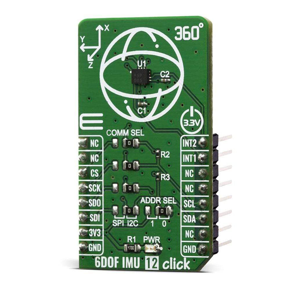
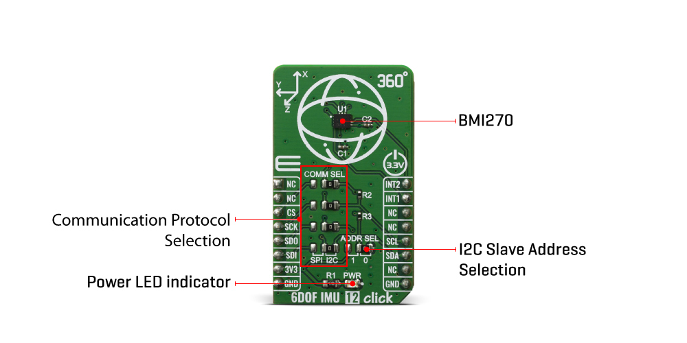
The 6DOF IMU 12 Click Board™ supports both SPI and I2C communication interfaces, allowing it to be used with a wide range of different MCUs. The communication interface can be selected by moving SMD jumpers grouped under the COM SEL to an appropriate position (SPI or I2C). The slave I2C address can also be configured by an SMD jumper when the Click board™ is operated in the I2C mode. An SMD jumper labelled as ADD SEL is used to set the least significant bit (LSB) of the I2C address.
SPECIFICATIONS
| Type | Acceleration,Gyroscope,Motion |
| Applications | An ideal choice for wearables, hearables, smart clothing, augmented / virtual reality. |
| On-board modules | The 6DOF IMU 12 Click Board™ uses the BMI270 IC, a low power inertial measurement unit, from Bosch Sensortec. |
| Key Features | 16-bit triaxial gyroscope and a 16-bit triaxial accelerometer, ensuring post-soldering sensitivity errors down to ± 0.4%. |
| Interface | I2C,SPI |
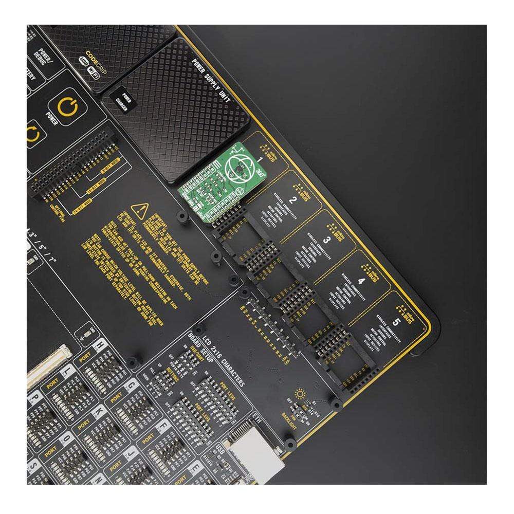
| Compatibility | mikroBUS |
| Click board size | M (42.9 x 25.4 mm) |
| Input Voltage | 3.3V |
PINOUT DIAGRAM
This table shows how the pinout of the 6DOF IMU 12 Click Board™ corresponds to the pinout on the mikroBUS™ socket (the latter shown in the two middle columns).
| Notes | Pin | Pin | Notes | ||||
|---|---|---|---|---|---|---|---|
| NC | 1 | AN | PWM | 16 | INT2 | Interrupt 2 | |
| NC | 2 | RST | INT | 15 | INT1 | Interrupt 1 | |
| SPI Chip Select | CS | 3 | CS | RX | 14 | NC | |
| SPI Clock | SCK | 4 | SCK | TX | 13 | NC | |
| SPI Data OUT | SDO | 5 | MISO | SCL | 12 | SCL | I2C Clock |
| SPI Data IN | SDI | 6 | MOSI | SDA | 11 | SDA | I2C Data |
| Power Supply | 3.3V | 7 | 3.3V | 5V | 10 | NC | |
| Ground | GND | 8 | GND | GND | 9 | GND | Ground |
ONBOARD SETTINGS AND INDICATORS
| Label | Name | Default | Description |
|---|---|---|---|
| LD1 | PWR | - | Power LED Indicator |
| JP1 | ADDR SEL | Right | I2C Slave Address LSB selection: left position 1, right position 0 |
| JP2-5 | COMM SEL | Right | Communication interface selection: left position SPI, right position I2C |
| General Information | |
|---|---|
Part Number (SKU) |
MIKROE-4073
|
Manufacturer |
|
| Physical and Mechanical | |
Weight |
0.02 kg
|
| Other | |
EAN |
8606018717248
|
Frequently Asked Questions
Have a Question?
Be the first to ask a question about this.