


Mikroelektronika d.o.o.
Monarch Adapter Click Board™
Monarch Adapter Click Board™
SKU: MIKROE-4057
Couldn't load pickup availability

Overview
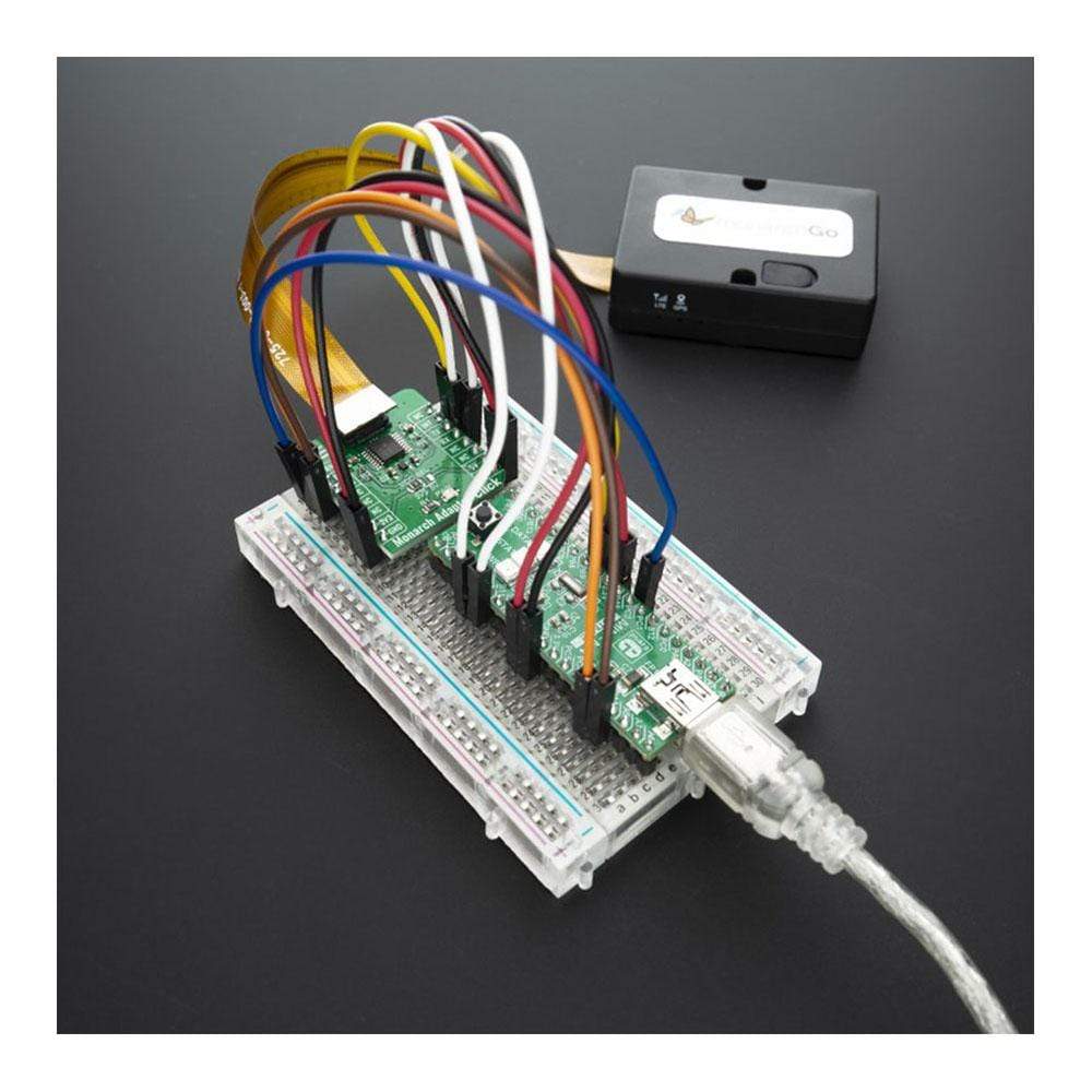
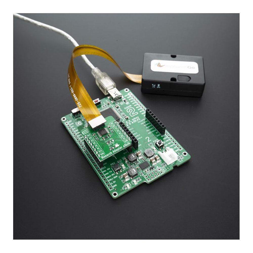
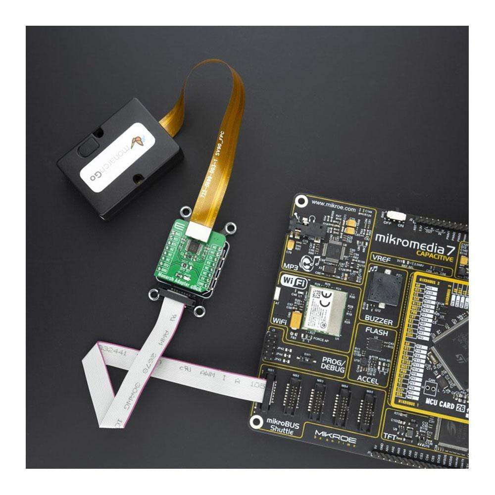
The Monarch Adapter Click Board™ is used to connect compatible Monarch Go LTE-M modems from Sequans to your development board or prototype device. This Click adapter provides a connection to the cloud server with AT commands. The Monarch Go LTE-M modem component with embedded antenna is perfectly suited for a broad range of IoT applications, including telemetry, vending machines, agriculture sensor applications, asset and transportation trackers, hardware tools, and home security monitoring applications.
The Monarch Adapter Click Board™ is supported by a mikroSDK compliant library, which includes functions that simplify software development. This Click Board™ comes as a fully tested product, ready to be used on a system equipped with the mikroBUS™ socket.
Downloads
Monarch GO and Monarch GO-GPS are certified for use on the Verizon network (LTE band 13) with roadmap for global band support. Monarch module is not delivered as part of the Click board package. For more information about module features please read Monarch GO module specification.
How Does The Monarch Adapter Click Board™ Work?
The Monarch Adapter Click Board™ is intended to help customers to successfully integrate and test their application based on Monarch Go. This Click adapter communication with your device through a serial UART interface and can exchange data with a cloud server using Verizon LTE network. The UART and GPIO pins of Monarch Go LTE-M modem is connected to one side of the level shifter, while the other side (Shifted) is connected to the respective mikroBUS™ UART and GPIO pins. However, the Monarch Go LTE-M modem series module is designed as the traditional DCE device (Data Communication Equipment) offering the full UART pin count, including the hardware flow control pins (CTS, RTS). These pins are routed to the mikroBUS™ CS (RTS) and the INT pin (CTS) and can be used in the MCU software if the hardware flow control is needed.
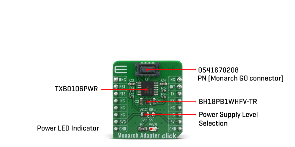
Digital sections of the Monarch Go LTE-M modem are internally supplied by 1.8V, so it is necessary to condition the communication bus lines which connect the host MCU with the module. The Monarch Adapter Click provide internal 1.8V via BH18PB1WHFV-TR LDO regulator from Rohm Semiconductor, output from its internal LDO regulator, providing a needed reference voltage for one side of the TXB0106, a 6bit bidirectional level shifting and voltage translator with automatic direction sensing, from Texas Instruments. The reference voltage for the other side of the level shifter is taken from the onboard SMD jumper, labelled as I/O Level This jumper is used to select between 3.3V and 5V from the mikroBUS™, depending on the used MCU type and its logic voltage level requirements.
SPECIFICATIONS
| Type | Adapter |
| Applications | The Monarch Adapter Click Board™ helps you to easily connect Sequans Monarch Go to your developement boards with mikroBUS sockets |
| On-board modules | 0541670208 connector from Molex |
| Key Features | Support SEQUANS Monarch Go modem |
| Interface | GPIO,UART |
| Compatibility | mikroBUS |
| Click board size | S (28.6 x 25.4 mm) |
| Input Voltage | 3.3V or 5V |
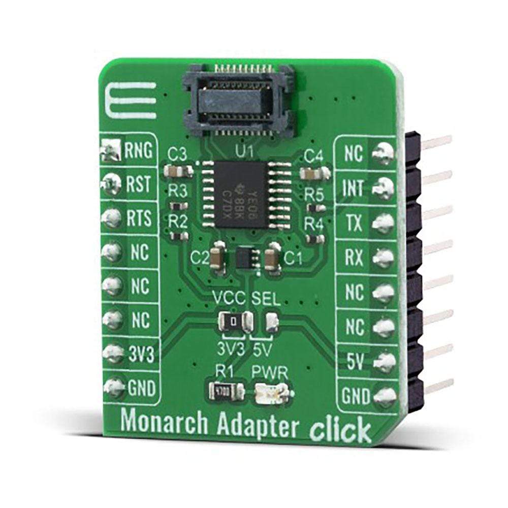
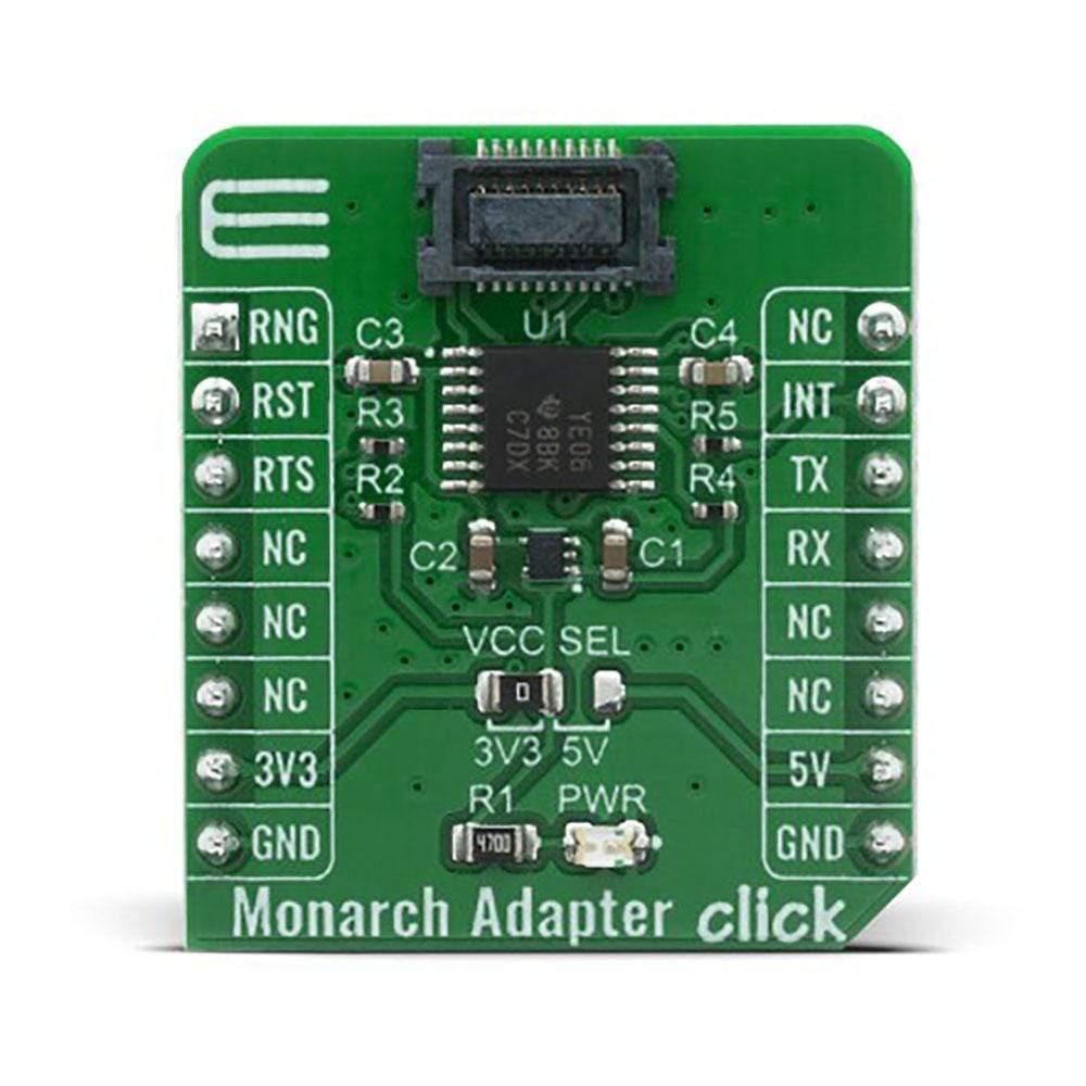
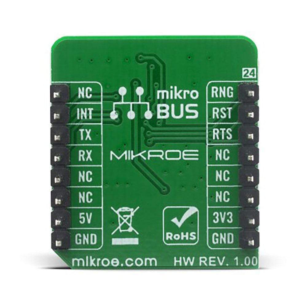
PINOUT DIAGRAM
This table shows how the pinout of the Monarch Adapter Click Board™ corresponds to the pinout on the mikroBUS™ socket (the latter shown in the two middle columns).
| Notes | Pin | Pin | Notes | ||||
|---|---|---|---|---|---|---|---|
| Ring signal | RNG | 1 | AN | PWM | 16 | NC | |
| Reset | RST | 2 | RST | INT | 15 | INT | Clear to Send |
| Ready to Send | RTS | 3 | CS | RX | 14 | TX | UART TX (transmit) |
| NC | 4 | SCK | TX | 13 | RX | UART RX (receive) | |
| NC | 5 | MISO | SCL | 12 | NC | ||
| NC | 6 | MOSI | SDA | 11 | NC | ||
| Power Supply | 3.3V | 7 | 3.3V | 5V | 10 | 5V | Power Supply |
| Ground | GND | 8 | GND | GND | 9 | GND | Ground |
ONBOARD SETTINGS AND INDICATORS
| Label | Name | Default | Description |
|---|---|---|---|
| LD1 | PWR | - | Power LED Indicator |
| JP1 | VCC SEL | Left | Power supply voltage selection: left position 3V3, right position 5V |
| General Information | |
|---|---|
Part Number (SKU) |
MIKROE-4057
|
Manufacturer |
|
| Physical and Mechanical | |
Weight |
0.02 kg
|
| Other | |
EAN |
8606018717149
|
Frequently Asked Questions
Have a Question?
Be the first to ask a question about this.