


Mikroelektronika d.o.o.
6DOF IMU 10 Click Board™
6DOF IMU 10 Click Board™
SKU: MIKROE-3934
Couldn't load pickup availability


Overview
The 6DOF IMU 10 Click Board™ is a 6 Degrees-of-Freedom inertial sensor module, that features a KMX62 sensor which consists of a tri-axial magnetometer (range ±2g / ±4g / ±8g / ±16g) plus a triaxial accelerometer (±1200µT). The accelerometer and magnetometer data can be accumulated in an internal 384-byte FIFO buffer and transmitted to the Application Processor. This Click Board™ can be used for applications that require movement and orientation features, navigation, such as screen orientation, machine/vibration analysis, game playing.
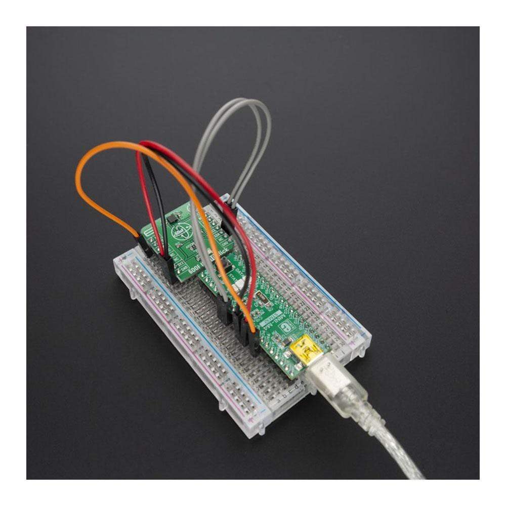
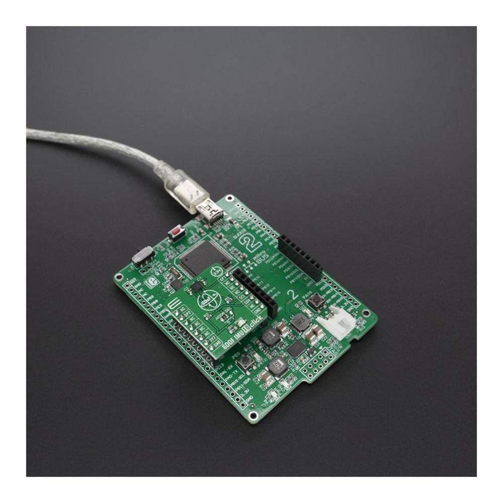
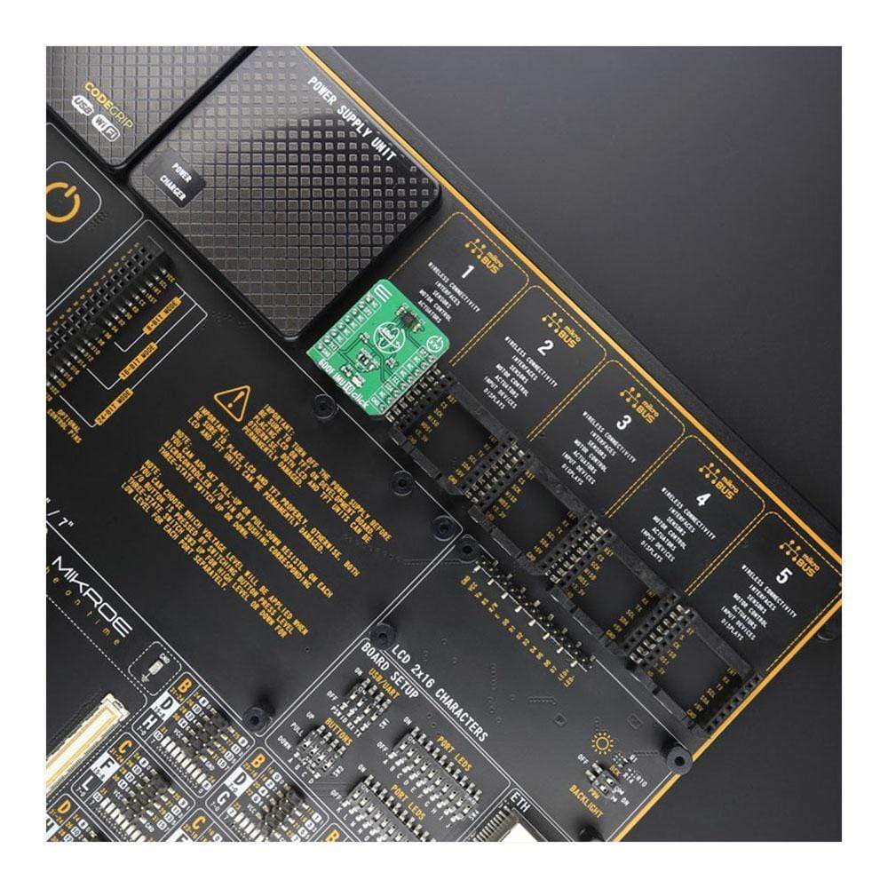
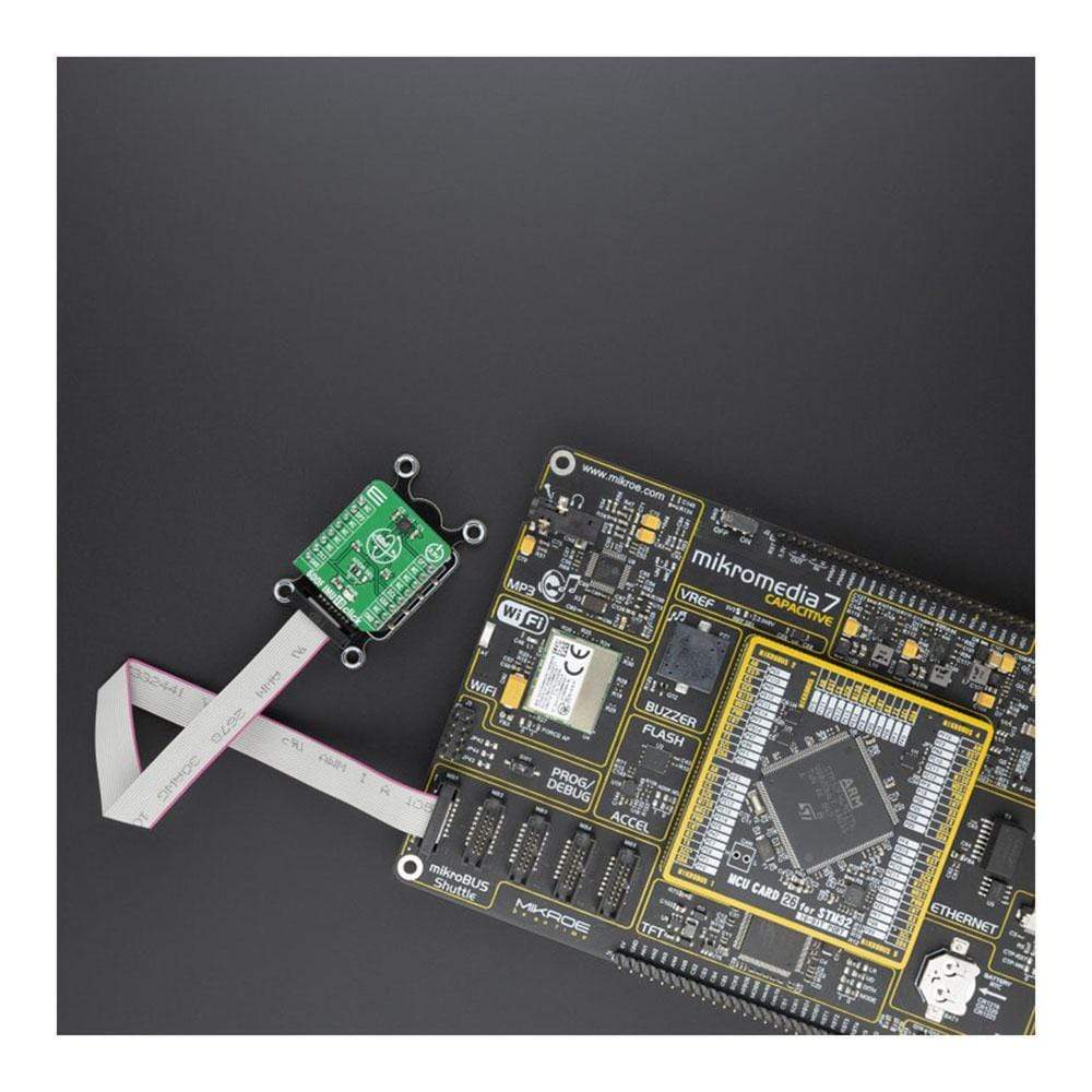
The 6DOF IMU 10 Click is supported by a mikroSDK compliant library, which includes functions that simplify software development. This Click Board™ comes as a fully tested product, ready to be used on a system equipped with the mikroBUS™ socket.
Downloads
How Does The 6DOF IMU 10 Click Board™ Work?
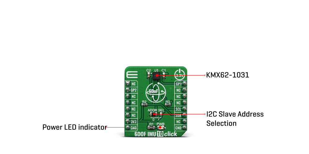
The 6DOF IMU 10 Click Board™ features the KMX62-1031 a 6 Degrees-of-Freedom inertial sensor from Kionix. It is based on the principle of a differential capacitance arising from acceleration-induced motion of the sense element, which utilizes common mode cancellation to decrease errors from process variation, temperature, and environmental stress. Capacitance changes are amplified and converted into digital signals which are processed by a dedicated digital signal processing unit.
The digital signal processor applies filtering, bias, and sensitivity adjustments, as well as temperature compensation. Magnetic sensing is based on the principle of magnetic impedance. The magnetic sensor detects very small magnetic fields by passing an electric pulse through a special electron spin aligned amorphous wire. Due to the high Curie temperature of the wire, the sensor's thermal performance shows excellent stability. Noise performance is excellent with bias stability over temperature. Bias errors resulting from assembly can be trimmed digitally by the user. These sensors can accept supply voltages between 1.7V and 3.6V, and digital communication voltages between 1.2V and 3.6V.
The Kionix KMX62 digital sensor can communicate on the I2C digital serial interface bus. This flexibility allows for easy system integration by eliminating analog-to-digital converter requirements and by providing direct communication with system processors. The I2C interface is compliant with high-speed mode, fast mode, and standard mode I2C protocols.
As previously mentioned, the KMX62 can communicate on an I2C bus. I2C is primarily used for synchronous serial communication between a Master device and one or more Slave devices. The system Master provides the serial clock signal and addresses Slave devices on the bus. The KMX62 always operates as a Slave device during standard Master-Slave I2C operation. I2C is a two-wire serial interface that contains a Serial Clock (SCL) line and a Serial Data (SDA) line. SCL is a serial clock that is provided by the Master, but can be held LOW by any Slave device, putting the Master into a wait condition. SDA is a bi-directional line used to transmit and receive data to and from the interface. Data is transmitted MSB (Most Significant Bit) first in 8-bit per byte format, and the number of bytes transmitted per transfer is unlimited. The I2C bus is considered free when both lines are HIGH.
SPECIFICATIONS
| Type | Motion |
| Applications | A accelerometer can be used to enable a variety of simultaneous features for Machine health, screen orientation, navigation. |
| On-board modules | KMX62-1031, a 6 Degrees-of-Freedom inertial sensor from Kionix |
| Key Features | 16-bit digital output, Internal 384-byte FIFO buffer |
| Interface | GPIO,I2C |
| Compatibility | mikroBUS |
| Click board size | S (28.6 x 25.4 mm) |
| Input Voltage | 3.3V |
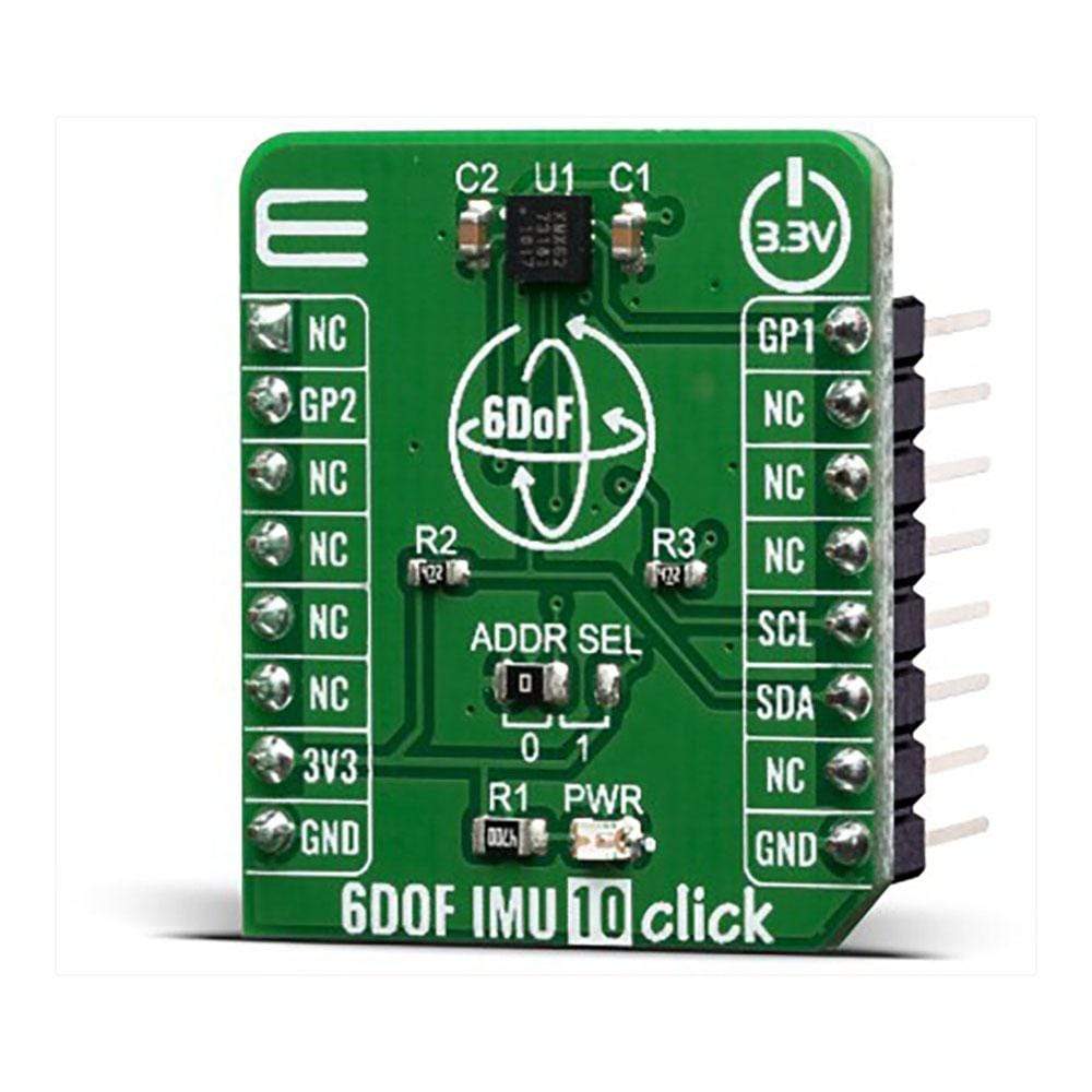
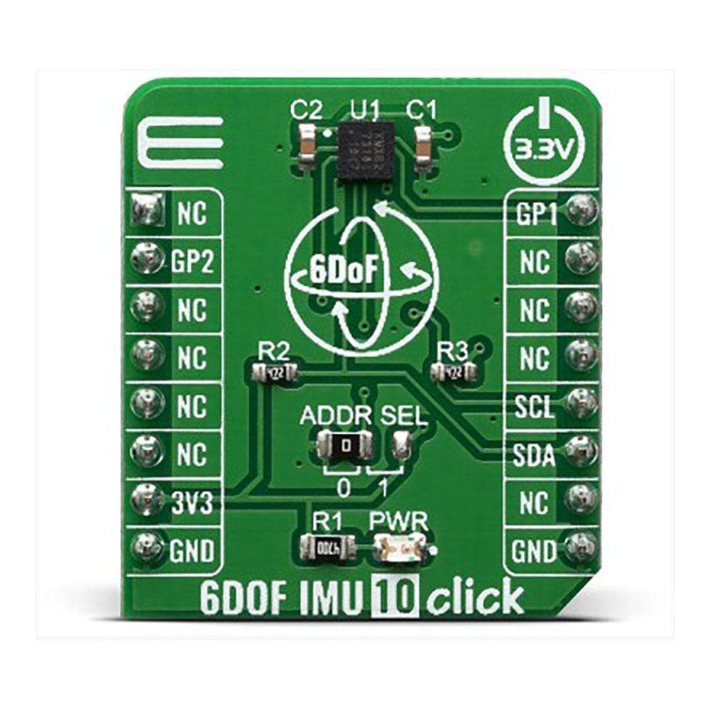
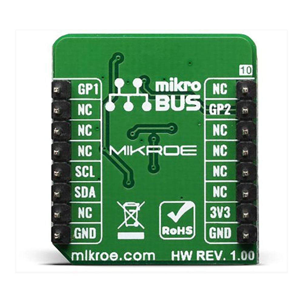
PINOUT DIAGRAM
This table shows how the pinout of the 6DOF IMU 10 Click Board™ corresponds to the pinout on the mikroBUS™ socket (the latter shown in the two middle columns).
| Notes | Pin | Pin | Notes | ||||
|---|---|---|---|---|---|---|---|
| NC | 1 | AN | PWM | 16 | GP1 | General Purpose #1 | |
| General Purpose #2 | GP2 | 2 | RST | INT | 15 | NC | |
| NC | 3 | CS | RX | 14 | NC | ||
| NC | 4 | SCK | TX | 13 | NC | ||
| NC | 5 | MISO | SCL | 12 | SCL | I2C Clock | |
| NC | 6 | MOSI | SDA | 11 | SDA | I2C Data | |
| Power Supply | 3.3V | 7 | 3.3V | 5V | 10 | NC | |
| Ground | GND | 8 | GND | GND | 9 | GND | Ground |
ONBOARD SETTINGS AND INDICATORS
| Label | Name | Default | Description |
|---|---|---|---|
| LD1 | PWR | - | Power LED Indicator |
| JP1 | ADDR SEL | Left | Select I2C address bit: Left postion 0, Right position 1 |
| General Information | |
|---|---|
Part Number (SKU) |
MIKROE-3934
|
Manufacturer |
|
| Physical and Mechanical | |
Weight |
0.017 kg
|
| Other | |
EAN |
8606018718924
|
Frequently Asked Questions
Have a Question?
Be the first to ask a question about this.