


Mikroelektronika d.o.o.
DAC 4 Click Board™
DAC 4 Click Board™
SKU: MIKROE-3707
Couldn't load pickup availability
Overview
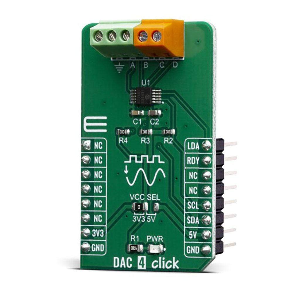
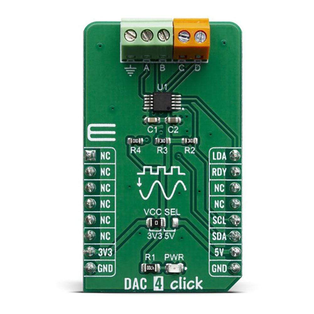
The DAC 4 Click Board™ carries Microchip’s MCP4728 IC, a Quad Digital-to-Analog Converter with nonvolatile (EEPROM) Memory. The digital value is converted to the appropriate voltage level in the range between GND and VCC, which is proportional to the received 12-bit number. MCP4726 also integrates EEPROM for storing DAC register and configuration bit values.
These options give a lot of flexibility which make it a perfect choice for an accurate and simple generation of analogue signals for various purposes, such as PLC/DCS modules, temperature and pressure control, medical and scientific instrumentation, chromatography and other similar applications, where accurate digital to analogue conversion is needed.
Downloads
The DAC 4 Click Board™ is an advanced 12bit multichannel digital to analog converter (DAC), with 4 single-ended/pseudo differential outputs. The Click Board™ has configurable internal voltage, which allows for unrestrained configuration of the device. The DAC 4 Click Board™ can be used for an digital to analog conversion in various applications, such as temperature and pressure control, medical and scientific instrumentation, chromatography and other similar applications, where accurate digital to analog conversion is needed.
How Does The DAC 4 Click Board™ Work?
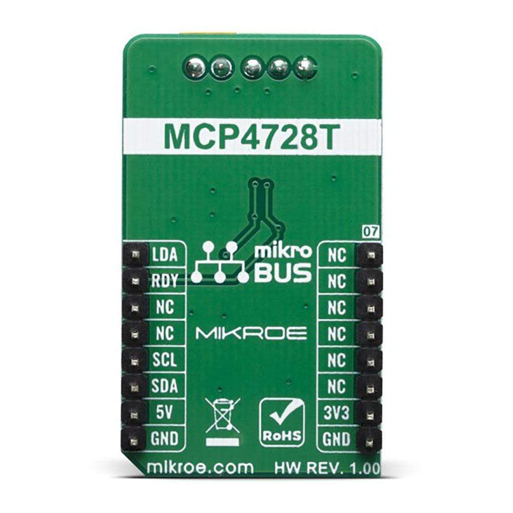
The main active component of the DAC 4 Click Board™ is the MCP4728, a quad, 12-bit voltage output Digital-to-Analog Convertor (DAC) with non-volatile memory (EEPROM), from Microchip. Its on-board precision output amplifier allows it to achieve rail-to-rail analog output swing. The DAC input codes, device configuration bits, and I2C address bits are programmable to the non-volatile memory (EEPROM) by using I2C serial interface commands. The non-volatile memory feature enables the DAC device to hold the DAC input codes during power-off time, allowing the DAC outputs to be available immediately after power-up with the saved settings.

The MCP4728 device has a high precision internal voltage reference (VREF = 2.048V). The internal reference can be selected by user, or external reference may be used (VDD) for each channel individually. This gives the ADC 4 Click Board™ good flexibility for use in various applications.
Each channel can be operated in Normal mode or Power-Down mode individually by setting the configuration register bits. In Power-Down mode, most of the internal circuits in the powered down channel are turned off for power savings, and the output amplifier can be configured to present a known low, medium, or high resistance output load. This device also includes a Power-on Reset (POR) circuit to ensure reliable power-up and an on-board charge pump for the EEPROM programming voltage.
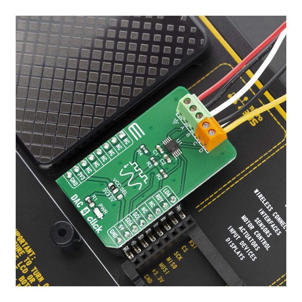
The MCP4728 has four output pins, which are routed to the output terminal blocks (TB1 and TB2). The output range of the DAC is 0 V to VREF or 0 V to 2×V REF. The communication with the main MCU is established over a two-wire I2C compatible serial interface, with standard (100 kHz), fast (400 kHz), or high speed (3.4 MHz) modes supported. The I2C lines (SCL and SDA) are routed to the dedicated mikroBUSpins. The LDA pin is multipurpose GPIO: It can be used as Synchronization input or for the device I2C address selection. RDY pin can also optionaly be used to monitor status of EEPROM programming activity.
The voltage level of the logic section can be selected via the VCCSEL jumper, between 3.3V and 5V. This allows for both 3.3V and 5V capable MCUs to use the I2C communication lines properly.
SPECIFICATIONS
| Type | DAC |
| Applications | Suitable for , temperature and pressure control, medical and scientific instrumentation, chromatography and other similar applications, where accurate digital to analog conversion is needed. |
| On-board modules | MCP4728, a quad, 12-bit voltage output Digital-to-Analog Convertor (DAC) with nonvolatile memory (EEPROM), from Microchip. |
| Key Features | high precision internal voltage reference, low-power Consumption, each channel separately configurable, power-on reset (POR) circuit, high speed I2C serial interface (up to 3.4 MHz), fast settling time |
| Interface | GPIO,I2C |
| Compatibility | mikroBUS |
| Click Board™ size | M (42.9 x 25.4 mm) |
| Input Voltage | 3.3V or 5V |
PINOUT DIAGRAM
This table shows how the pinout on DAC 4 Click Board™ corresponds to the pinout on the mikroBUS socket (the latter shown in the two middle columns).
| Notes | Pin | Pin | Notes | ||||
|---|---|---|---|---|---|---|---|
| NC | 1 | AN | PWM | 16 | LDA | Multipurpose GPIO | |
| NC | 2 | RST | INT | 15 | RDY | Ready Out | |
| NC | 3 | CS | RX | 14 | NC | ||
| NC | 4 | SCK | TX | 13 | NC | ||
| NC | 5 | MISO | SCL | 12 | SCL | I2C serial clock | |
| NC | 6 | MOSI | SDA | 11 | SDA | I2C serial data | |
| Power Supply | 3.3V | 7 | 3.3V | 5V | 10 | 5V | Power supply |
| Ground | GND | 8 | GND | GND | 9 | GND | Ground |
ONBOARD SETTINGS AND INDICATORS
| Label | Name | Default | Description |
|---|---|---|---|
| LD1 | PWR | - | Power LED Indicator |
| JP1 | VCC SEL | Left | Logic level selection, left position 3.3V, right 5V |
DAC 4 Click Board™ ELECTRICAL SPECIFICATIONS
| Description | Min | Typ | Max | Unit |
|---|---|---|---|---|
| Analog output voltage | 0 | 5 | V | |
| Settling Time | - | 6 | - | μs |
| Sampling bit depth | - | 12 | - | bits |
| Operating supply voltage | 2.7 | 3.3 | 5.5 | V |
| General Information | |
|---|---|
Part Number (SKU) |
MIKROE-3707
|
Manufacturer |
|
| Physical and Mechanical | |
Weight |
0.019 kg
|
| Other | |
EAN |
8606018716654
|
Frequently Asked Questions
Have a Question?
Be the first to ask a question about this.