


Mikroelektronika d.o.o.
AudioMUX Click Board™
AudioMUX Click Board™
SKU: MIKROE-3344
Couldn't load pickup availability
Overview
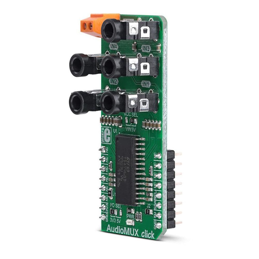
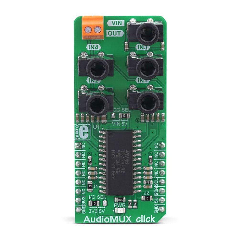
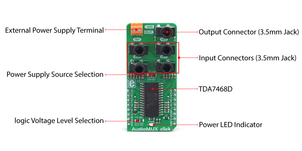
The AudioMUX Click Board™ Board™ is a sound processing Click Board™ with digital controls, based on the TDA7468D IC. It can be used to select one of four audio input channels, adjust its frequency response and volume, and send it to the output. There is also a BASS ALC section implemented on this IC, keeping the base in control even on higher volume settings. Independent LEFT and RIGHT channel volume control, complete control over the I2C interface, a full set of 3.5mm vertical jack connectors on-board All these features make this Click Board™ a very good solution for the development of all kinds of audio applications.
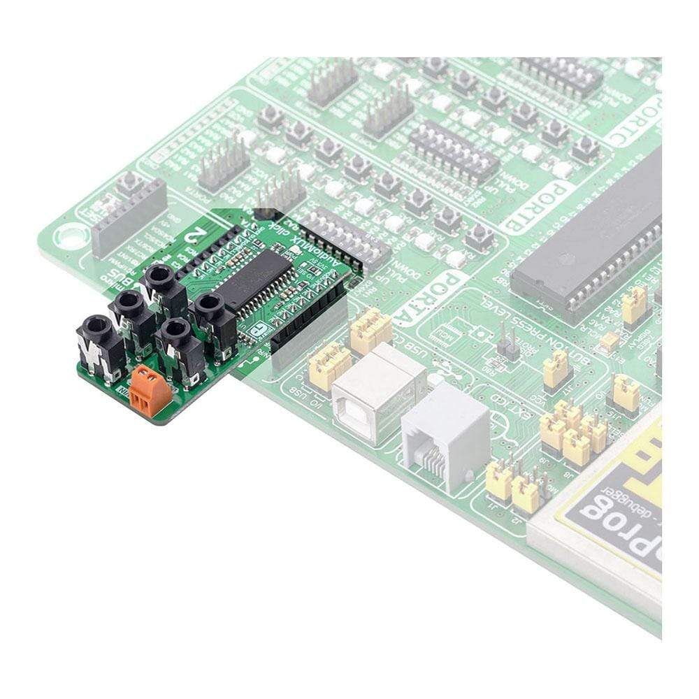
The AudioMUX Click Board™ is supported by a mikroSDK compliant library, which includes functions that simplify software development. This Click Board™ comes as a fully tested product, ready to be used on a system equipped with the mikroBUS socket.
Downloads
Featuring a set of 3.5mm vertical jack connectors onboard, it allows a simple connection to an existing audio chain. Because of its very good sound characteristics, including 0.01% of total harmonic distortion (THD), signal to noise ratio (SNR) of 100dB, 84dB of maximum attenuation, and more, the AudioMUX Click Board™ represents an ideal solution for developing and building audio applications that can be used for various HiFi systems, home stereo components, computer speakers with selectable input, and many other similar audio applications that require a digitally controlled input selection and audio processing.
How Does The AudioMUX Click Board™ Work?
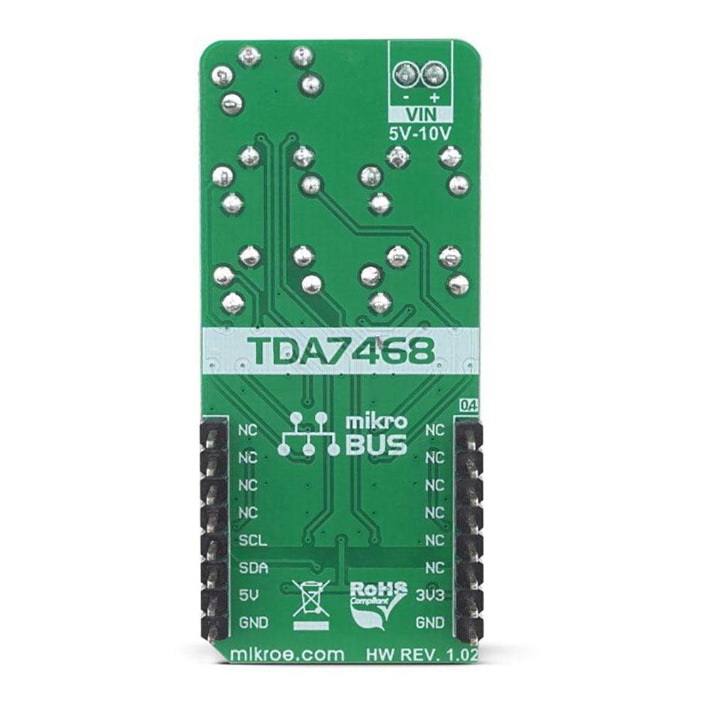
The AudioMUX Click Board™ is based on the TDA7468D IC from STMicroelectronics, which is a two-band digitally controlled high-quality audio processor with BASS ALC feature and a four-channel input selector. This integrated audio processor is quite popular, and it can be found in several brands of HiFi and home stereo systems. Despite its simplicity, it offers a full set of options required for a realization of the four-channel audio multiplexer with volume, balance, and tone controls. The TDA7468D IC is digitally controlled over the I2C interface; however, the internal sections are purely analog circuits, with a separate analog GND reference.
There are four input channels which can be selected over the I2C interface. The IC accepts up to 2.5V peak to peak at its inputs. The impedance of the input terminals is 50 kΩ, and each input is decoupled by a 440nF capacitor. There are not many registers in this IC, which makes the firmware development very easy. Each channel is routed to a vertically mounted 3.5mm jack, which allows the AudioMUX Click Board™ to be easily interfaced to an existing audio chain.
Some registers have a single function, while others are used to control more functions. The datasheet of the TDA7468D clearly explains each register and its functions.
After the input is selected by setting the specific bits in the INPUT SELECT register, the audio signal is routed to the first gain stage. It is possible to adjust the gain of the input signal up to +14dB, in 2dB steps. This is very useful when the amplitude of the input signal needs to be adjusted (gain staging)
The signal is then fed to the first (pre-EQ) volume control section which is able to attenuate the signal down to -63dB, in 1dB steps. If the signal is too high, a clipping might occur when the equalization is applied in the next section. Therefore, lowering the volume in this section will allow more headroom for the equalizer (EQ) section. The volume in this section is determined by the first 6 bits of the volume control register, referred to as the VOLUME 1 bitfield. The last 4 bits are related to the post EQ volume section and are referred to as the VOLUME 2 bitfield. Both volume sections feature independent volume control registers (VOLUME LEFT and VOLUME RIGHT), allowing balance function to be implemented.
The EQ sections can adjust bass and treble frequencies in the range from -14dB to +14dB, in 2dB steps. The frequency response of these sections is determined by external RC elements. The Click board™ has these values optimally selected for the best performance. The low-frequency range is processed by a T type bandpass filter with its center frequency at around 32Hz, while the high-frequency range is processed by a high pass filter with the -3dB attenuation point at about 3kHz. A single register is used to control the entire EQ section (TREBLE & BASS register).
After the sound is processed by the EQ section, there is an output stage, which allows attenuation of -24dB in 8dB steps. This post-EQ stage allows the volume to be fine-tuned and adjusted to the input stage of an audio amplifier. The volume of this section is controlled by the VOLUME 2 bitfield, in two independent registers, one for each channel (VOLUME LEFT and VOLUME RIGHT)
The BASS ALC is basically a compressor, applied to the low-frequency range. It is a very useful feature, keeping the low-frequency content even when the volume is set to a high value. The low-frequency band will be dynamically attenuated when the programmed threshold value is exceeded, after the programmed attack time. The BASS ALC is automatically turned off when the EQ is set to attenuate low frequencies, as there is no point to use it in that case. There are also some additional settings for the BASS ALC function. For the complete list of features, please refer to the datasheet of the TDA7468D. The BASS ALC function is controlled by bits in the BASS ALC register.
The output of the TDA7468D IC can be enabled or disabled by a single control bit of the OUTPUT register.
When building audio applications in a purely digital surround, special care should be taken to isolate the audio signal path as much as possible, in order to avoid any noise at the output. The AudioMUX Click Board™ is equipped with two 0 Ω resistors (jumpers) at strategic positions. These jumpers are labeled as J1 and J2. They can be replaced either with resistors or with inductors. J1 jumper connects analog and digital GND in a single point. If the reference GND is noisy, using a clean external power supply (PSU), combined with a small resistance value up to 100 Ω in the place of J1, can help in reducing the output noise. The second jumper (J2) can be replaced with a ferrite bead or an inductor, which can help to filter the noise at the positive rail of the power supply. The noise at the output can also be a result of improper gain staging (e.g. all the gains are at their maximum value). The TDA7468D itself is not very noisy, only about 15 µV max.
The SMD jumper labeled as VCC SEL is used to select the power supply. If set to 5V, the analog section of the TDA7468D IC will be powered from the mikroBUS™ +5V rail. When the jumper is set to VIN, the analog section of the TDA7468D IC will be power from an external power source, connected to the VIN screw terminal. The external power source voltage should be within the range between 5V and 10V.
The logic section of the TDA7468D will always be powered from the mikroBUS™, regardless of the VCC SEL position. However, it is still possible to select the voltage level for the I2C bus, allowing communication with a wide range of different MCUs. This can be done by switching the SMD jumper labeled as I/O SEL to either 3.3V or 5V.
SPECIFICATIONS
| Type | Signal Processing |
| Applications | It can be used in various HiFi systems, home stereo components, computer speakers with selectable input, and many other similar audio applications that require a digitally controlled input selection and audio processing. |
| On-board modules | TDA7468D IC from STMicroelectronics, a two-band digitally controlled high-quality audio processor with BASS ALC feature and the input selector |
| Key Features | High quality audio output, integrated four-channel input selector with tone controls, each connector is a high-quality vertically mounted 3.5mm standard stereo jack, good frequency response, low THD and SNR, it can be directly implemented into the existing stereo system, etc. |
| Interface | I2C |
| Compatibility | mikroBUS |
| Click board size | L (57.15 x 25.4 mm) |
| Input Voltage | 3.3V or 5V |
Pinout Diagram
This table shows how the pinout of the AudioMUX Click Board™ corresponds to the pinout on the mikroBUS™ socket (the latter shown in the two middle columns).
| Notes | Pin | Pin | Notes | ||||
|---|---|---|---|---|---|---|---|
| NC | 1 | AN | PWM | 16 | NC | ||
| NC | 2 | RST | INT | 15 | NC | ||
| NC | 3 | CS | RX | 14 | NC | ||
| NC | 4 | SCK | TX | 13 | NC | ||
| NC | 5 | MISO | SCL | 12 | SCL | I2C Clock | |
| NC | 6 | MOSI | SDA | 11 | SDA | I2C Data | |
| Power Supply | 3V3 | 7 | 3.3V | 5V | 10 | 5V | Power Supply |
| Ground | GND | 8 | GND | GND | 9 | GND | Ground |
ONBOARD SETTINGS AND INDICATORS
| Label | Name | Default | Description |
|---|---|---|---|
| LD1 | PWR | - | Power LED indicator |
| JP1 | VCC SEL | Right | Power supply input selection: left position VIN connector, right position 5V from the mikroBUS™ |
| JP2 | I/O SEL | Left | Logic level voltage selection: left position 3.3V, right position 5V |
| J1 | J1 | Populated | Jumper between the analog and digital GND |
| J2 | J2 | Populated | Jumper in series with the mikroBUS™ 5V power supply rail |
| General Information | |
|---|---|
Part Number (SKU) |
MIKROE-3344
|
Manufacturer |
|
| Physical and Mechanical | |
Weight |
0.025 kg
|
| Other | |
EAN |
8606018714438
|
Frequently Asked Questions
Have a Question?
Be the first to ask a question about this.